Do you have a question about the Amphenol HVSL60061 Series and is the answer not in the manual?
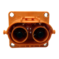
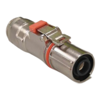
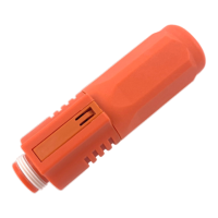
Diagram illustrating the components of the HVSL600061 series connector.
Detailed list of parts, part numbers, and quantities for HVSL600061 series connectors.
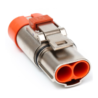
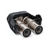
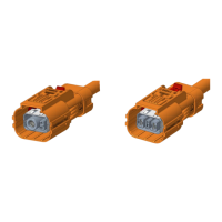
Diagram illustrating the components of the HVSL630062 series connector.
Detailed list of parts, part numbers, and quantities for HVSL630062 series connectors.
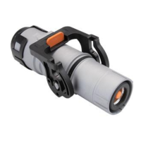
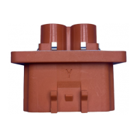
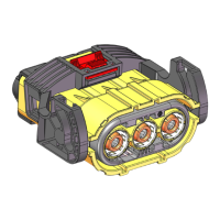
Diagram illustrating the components of the HVSL280063 series connector.
Detailed list of parts, part numbers, and quantities for HVSL280063 series connectors.
Guidance on selecting wire specifications based on the connector model.
Instructions for cutting and stripping wire insulation to specific dimensions.
Steps for crimping signal terminals, with emphasis on orientation and retention force.
Table detailing cable part numbers and their corresponding outer diameters.
Sequence for sliding cable protection and shielding components onto the cable.
Instructions for stripping the power cable jacket to specific lengths.
Steps for positioning the inner ferrule, folding braid, and applying copper foil.
Instructions for crimping terminals, including visual checks and acceptance criteria.
Steps for inserting signal contacts and securing them with a plastic chock.
Process for inserting power contacts into the connector housing.
Steps for attaching the shielding shell to the connector core.
Instructions for positioning and crimping the outer shielding ferrule.
Process for inserting the prepared cable assembly into the connector housing.
Steps for assembling the spacer, cable seal, and end cap onto the connector.
Guidance on selecting wire specifications based on the connector part number.
Instructions for cutting and stripping wire insulation to specific dimensions.
Steps for crimping signal terminals, with emphasis on orientation and retention force.
Table detailing cable part numbers and their corresponding outer diameters.
Sequence for sliding cable protection and shielding components onto the cable.
Instructions for stripping the cable jacket to specific dimensions.
Steps for positioning the inner ferrule, folding braid, and applying copper foil.
Instructions for stripping wire insulation to specific dimensions.
Instructions for crimping terminals, including retention force requirements.
Steps for inserting signal contacts into the connector housing, ensuring correct orientation.
Process for inserting power contacts and mounting the chock onto the connector.
Steps for attaching the shielding shell to the connector assembly.
Instructions for positioning and crimping the outer shielding ferrule.
Process for inserting the prepared cable assembly into the connector housing.
Steps for assembling the spacer, cable seal, and end cap onto the connector.
Steps for inserting the cable seal into the connector housing.
Final step of mounting the end cap onto the connector assembly.
Guidance on selecting cable specifications based on the connector part number.
Instructions for cutting and stripping wire insulation to specific dimensions.
Steps for crimping signal terminals, with emphasis on orientation and retention force.
Table detailing power cable part numbers and their corresponding outer diameters.
Sequence for sliding cable protection and shielding components onto the cable.
Instructions for stripping the cable jacket to specific dimensions.
Steps for positioning the inner ferrule, folding braid, and applying copper foil.
Instructions for stripping wire insulation to specific dimensions.
Instructions for crimping terminals, including retention force requirements.
Steps for inserting signal contacts into the connector housing, ensuring correct orientation.
Process for inserting power contacts and mounting the chock onto the connector.
Steps for attaching the shielding shell to the connector assembly.
Instructions for positioning and crimping the outer shielding ferrule.
Process for inserting the prepared cable assembly into the connector housing.
Steps for assembling the spacer, cable seal, and end cap onto the connector.
Steps for inserting the cable seal into the connector housing.
Final step of mounting the end cap onto the connector assembly.
Details on hi-pot and insulation resistance testing procedures and parameters.
Procedure for performing a 100% continuity test on the product.
Requirement for 100% IP67 water proof testing when matched with a socket.
Tool for crimping contacts and shield rings, model APSM240-10.
Machine for crimping contacts (EV-E500) and its applicator (EV-M001).
Various dies for mounting on the applicator for signal and power contacts.
Tools for extracting signal and power contacts, models HVTOOL-600-001, HVTOOL-630-001, HVTOOL-280-001.
| Brand | Amphenol |
|---|---|
| Model | HVSL60061 Series |
| Category | Cables and connectors |
| Language | English |