Do you have a question about the Amphenol PL18 50 Series and is the answer not in the manual?
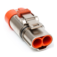
First component in the package contents list, for shielding the assembly.
Second component, an insulating sleeve with HVIL contact for high voltage interlocking.
Third component, an R4 terminal holder featuring an anti-rotation chamfer.
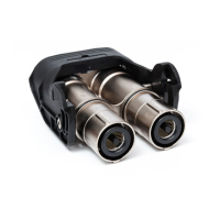
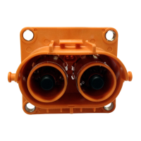
Fourth component, consisting of two lock housing pieces for securing the assembly.
Fifth component, a plastic clamp spring for securing parts within the assembly.
Sixth component, a coil spring for mechanical function within the connector.
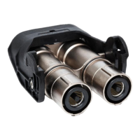
Seventh component, an outer copper ring for electrical connection or grounding.
Eighth component, an inner copper ring for electrical connection or grounding.
Ninth component, a metal gasket for sealing or electrical contact.
Tenth component, a sealing ring for environmental protection.
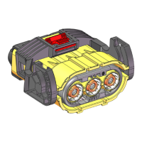
Eleventh component, an end cap to close off the connector assembly.
Prepare cable by selecting and cutting to the appropriate size as per production plan.
Strip cable insulation and jacket according to specified lengths in Table 2.
Install inside copper ring and outer copper ring, then crimp according to specifications.
Load and crimp the R4 holder onto the cable end, ensuring specified gap.
Install the coil spring onto the outer copper ring.
Place lock housing parts into the space between terminal and insulation.
Insert the insulation sleeve into the R4 holder, ensuring it contacts the bottom.
Install the plastic clamp spring between the insulation sleeve and lock housing.
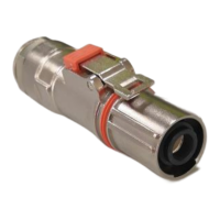
Connect the shield shell assembly to the prepared plug components.
Insert insulation sleeve into shield shell, ensuring HVIL position and clamp spring.
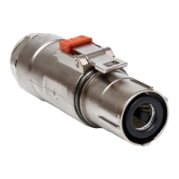
Install metal gasket, sealing, and end cap to complete one end assembly.
Perform Insulation Resistance and Dielectric Withstand Voltage tests post-assembly.
Caution on reviewing electrical test parameters against application requirements for safety.
Recommendations for using protective covers during connector and harness handling.
| Body Plating | Nickel |
|---|---|
| Contact Material | Brass |
| Contact Plating | Silver |
| Mounting Type | Cable |
| Series | PL18 |
| Voltage Rating | 500V |