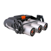
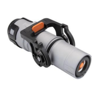
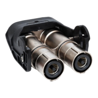
The Amphenol PowerLok G2 90D Plug Connector is a robust and versatile electrical connector designed for industrial applications, particularly in the automotive and transportation sectors. This manual details the assembly process, technical specifications, and maintenance guidelines for the connector, ensuring safe and reliable operation.
Function Description
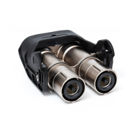
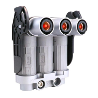
The PowerLok G2 90D Plug Connector serves as a critical interface for transmitting power in high-voltage and high-current systems. Its design emphasizes reliability, safety, and ease of assembly, making it suitable for demanding environments. The connector features a 90-degree plug orientation, which can be advantageous for space-constrained installations or specific cable routing requirements. It is designed to connect to corresponding receptacles, forming a secure and electrically sound connection. The modular design allows for flexibility in cable size and termination, accommodating various application needs.
Important Technical Specifications
The connector system is available in two main series: 300 Series and 300S Series, each supporting different cable sizes and electrical characteristics.
- Cable Size:
- 300 Series: 50mm²
- 300S Series: 70mm²
- Accepted Cable OD (mm):
- 50mm²: 14.9±0.3
- 70mm²: 17.0±0.3
- Crimp Height (mm) for Inner Pin:
- 50mm²: 18.0±0.25
- 70mm²: 20.3±0.25
- Retention Force (N) for Inner Pin:
- Crimp Height (mm) for R4 Terminal Assembly:
- 50mm²: 11.34 ±0.25
- 70mm²: 13.18 ±0.25
- Retention Force (N) for R4 Terminal Assembly:
- 50mm²: 2800N
- 70mm²: 3400N
- Insulation Resistance:
- Cable (power) to shell: > 500 MΩ (Test voltage: 1000 VDC, Test time: 5S)
- Cable (power) to HVIL: > 500 MΩ (Test voltage: 1000 VDC, Test time: 5S)
- Cable (power) to high voltage mutual exclusion: > 500 MΩ (Test voltage: 1000 VDC, Test time: 5S)
- HVIL to shell: > 100 MΩ (Test voltage: 1000 VDC, Test time: 1S)
- Dielectric Withstand Voltage (Leakage Current):
- Cable (power) to shell: < 5 mA (Test voltage: 5000 VDC, Test time: 10S)
- Cable (power) to HVIL: < 5 mA (Test voltage: 5000 VDC, Test time: 10S)
- Cable (power) to high voltage mutual exclusion: < 5 mA (Test voltage: 5000 VDC, Test time: 10S)
- HVIL to shell: < 5 mA (Test voltage: 500 VDC, Test time: 1S)
The connector is designed to meet PowerLok and peak 1000VDC rating, with test parameters exceeding the limit of other components/materials used on the cable assembly or device.
Usage Features
The assembly process for the PowerLok G2 90D Plug Connector is detailed in a step-by-step manner, emphasizing precision and the use of specific tools.
- Cable Preparation: Cables must be stripped to precise lengths. For 50mm² cables, the stripping length for the outer jacket is 32±1mm, and for the inner conductor, it's 17±1mm. For 70mm² cables, these lengths are 32±1mm and 17±1mm, respectively. The chamfer faces right in the graphic indicate the orientation for stripping.
- Crimping Copper Ring: The inner copper ring is crimped onto the stripped cable. It's crucial to ensure the shield line is covered on the surface of the copper ring and that the distance from the front end to the outer front end of the copper ring is 0mm after crimping. The outer copper ring is then crimped, ensuring the ends are level with each other before crimping. Hydraulic press tools are specified for crimping, with specific die numbers for different cable sizes (e.g., 195150D50 for 50mm² and 22020150D70 for 70mm²).
- Crimping Coil Spring: A coil spring is installed onto the outer copper ring.
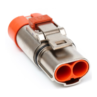
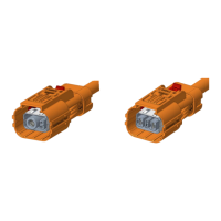
- Crimping R4 Terminal Assembly: The R4 terminal assembly is crimped onto the cable. This step also requires a hydraulic press and specific die numbers (e.g., L131301D50 for 50mm² and L1321531D70 for 70mm²). The key mark on the connector indicates the color (Orange for X, Black for Y).
- Insulation Sleeve Installation: An insulation sleeve is installed onto the terminal, sliding it into the terminal.
- Shell Assembly: The front end of the connector is secured with a torque of 10~12N·M. The sealing is pushed to the bottom of the shield shell assembly.
- Tail Shell Assembly: The tail shell assembly is attached.
- Final Assembly (Manual Press/Pneumatic Press):
- Place the tail shell assembly on a desktop.
- Push the sealing of the connecting head into the inner part of the tail shell assembly.
- Insert the product into the fixture (T60014 for pneumatic press, T00281 for manual press).
- Crank the handle to press the connector into the tail housing assembly and hold.
- Release the pneumatic switch (or manual press pliers) and continue to press the joint down to confirm the installation is in place, listening for an audible click.
- Cable Routing: The connector is moved to the indicated position, and the gasket metal of the other two cables is installed.
- Latch Assembly: The metal gasket is pushed to close the sealing. The connector is placed horizontally on the desktop. The Clamp W is installed at the end of the connector, followed by the inversion of the connector. The Clamp W/O is installed at the end of the connector. The gap between the two locking blocks should be less than 1mm. Two M6×18 screws, M6 spring washers, and M6 flat washers are assembled. The screw in the upper position is locked with a torque of 3N·M. Finally, the batch is turned around to lock another lock hole.
- Iron Shell Assembly: The two ends of the holes are aligned with the corresponding positions of the iron shell and loaded into the iron shell, completing the assembly.
Maintenance Features
The manual emphasizes the importance of proper assembly and regular testing to ensure the long-term reliability and safety of the connector.
- Insulation Resistance and Dielectric Withstand Voltage Tests: After assembly, these tests are mandatory to confirm the quality of the connection and insulation. The specified test voltages and times must be adhered to.
- Recommended Electrical Tests: All electrical tests and parameters should be reviewed against end application requirements to ensure safety and prevent damage to other components.
- Plug Dust Cover and Protective Cover: During handling and high-voltage harness handling, it is recommended to use a plug dust cover and plug protective cover to avoid bumping and damage. The HVIL cap must be removed before use.
- Crimp Quality: Regular checks of crimp height and retention force are crucial for maintaining a reliable connection. Customers need to reconfirm cross section on crimping area and pull out force test to confirm the quality of crimp process.
- Customized Cable: For customized cable with H+S material, customers should refer to Section 1-1 for details of H+S cable part numbers and contact Amphenol for support.
- Tooling: The use of specified hydraulic press tools and dies is critical for proper crimping. Regular maintenance and calibration of these tools are essential for consistent quality.
By following these detailed instructions and adhering to the specified technical parameters, users can ensure the optimal performance, safety, and longevity of the Amphenol PowerLok G2 90D Plug Connector in their applications.