EasyManua.ls Logo

Amphenol ePower-lite C10-765779-3XS1 - User Manual

Amphenol ePower-lite C10-765779-3XS1
6 pages
Print Icon
To Next Page IconTo Next Page
Loading...
CABLE ASSEMBLY WORK INSTRUCTION
ePower-lite 5.7mm 3-Port Connector
Part Numbers:
C10-765779-3XS1
C10-765779-3XS2
Revision Description Issue Date
A lnitial release 2021/08/16
AI-17
Question and Answer IconNeed help?

Do you have a question about the Amphenol ePower-lite C10-765779-3XS1 and is the answer not in the manual?

Summary

ePower-lite 5.7 mm 3-Port Connector Assembly Instructions

Part 1: Plug Assembly

Part 2: Plug Assembly

Shielded Wire Stripping

Stripping the jacket of the shielded wire according to specified length L1.

Mount Rear Inside Shield Ring

Mounting the rear inside shield ring (Part 4) onto the wire.

Cutting Shield Wire

Cutting the shield wire to a specified retention length L2.

Turn Back Shielding Wire

Turning the shielding wire back over the cable.

Install Rear Cover and Grommet

Installing the rear cover (Part 6) and rear grommet (Part 5) in sequence.

Mount Rear Cover (Part 3)

Mounting the rear cover (Part 3) onto the assembly.

Crimp Rear Shield Outside Ring

Crimping the rear shield outside ring with specified length and distance.

Remove Film Layer and Cut Insulation

Removing the film layer and cutting the insulation to specified length L3.

Mount Plug Contact Assembly

Mounting the plug contact assembly (Part 2) onto the prepared wire.

Crimp Rear Shield

Pulling wires and crimping the rear shield (Part 5) with specified length.

Final Assembly and Testing

Assembling remaining cables, rear sealing grommet, rear cover, and performing insulation/DWV tests.

Overview

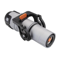
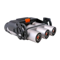
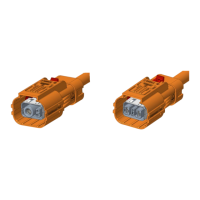
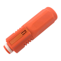
The Amphenol Industrial ePower-lite 5.7mm 3-Port Connector is a robust cable assembly designed for industrial applications, facilitating secure and reliable electrical connections. This manual outlines the assembly process and provides critical technical specifications for proper installation and maintenance.

Function Description

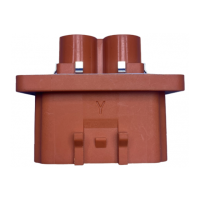
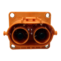
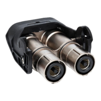
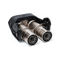
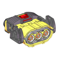
The ePower-lite 5.7mm 3-Port Connector serves as a crucial interface for power transmission in demanding industrial environments. It is designed to connect three cables, ensuring a secure and shielded connection. The assembly involves several components, including a plug shell, plug contact assembly, rear outside shield ring, rear inside shield ring, rear grommet, and a rear cover. The primary function is to provide a durable and electrically sound connection while offering protection against environmental factors and mechanical stress through its multi-layered shielding and robust housing. The connector is specifically engineered to handle high power applications, as indicated by the recommended cable pullout forces and the necessity for specific crimping procedures.

Important Technical Specifications

The connector supports two primary wire sizes: 16 mm² and 25 mm². Each wire size has specific insulation and cable jacket diameter requirements, as well as recommended minimum cable pullout forces.

For 16 mm² wire:

  • Insulation Diameter: 8.1 ± 0.2 mm
  • Shield Wire Diameter: 0.12 REF (reference)
  • Cable Jacket Diameter: 11.2 ± 0.3 mm
  • Recommended Min. Cable Pullout Force: 1500 N

For 25 mm² wire:

  • Insulation Diameter: 10.2 ± 0.2 mm
  • Shield Wire Diameter: 0.12 REF (reference)
  • Cable Jacket Diameter: 13.9 ± 0.3 mm
  • Recommended Min. Cable Pullout Force: 1900 N

The assembly process involves precise cutting and crimping dimensions:

  • Jacket Stripping Length (L1): 29.5 ± 0.5 mm
  • Shield Wire Cutting Retention Length (L2): 9.5 ± 0.5 mm
  • Film Layer/Insulation Cutting Length (L3): 9 ± 0.5 mm

Crimping specifications are critical for ensuring proper electrical contact and mechanical retention. For the rear shield outside ring:

  • Recommended Crimp Length: 4.5 ± 0.5 mm
  • Recommended Crimp Length of Side S (for both 16mm² and 25mm²): 6.0
  • Recommended Crimp Dist Across Flats F:
    • 16mm²: 11.0 ± 0.1 mm
    • 25mm²: 11.0 ± 0.1 mm
  • Recommended Min. Pullout Force (for both 16mm² and 25mm²): 150 N

For the rear shield (Part 5) after pulling out one wire and loading:

  • Recommended Crimp Length: 8.0 ± 0.5 mm
  • Gap Reference: 1.0 mm
  • Recommended Crimp Length of Side S (for both 16mm² and 25mm²): 6.0
  • Recommended Crimp Dist Across Flats F:
    • 16mm²: 6.5 ± 0.1 mm
    • 25mm²: 7.5 ± 0.1 mm
  • Recommended Min. Pullout Force:
    • 16mm²: 1500 N
    • 25mm²: 1900 N

The manual specifies post-assembly electrical tests:

  • Insulation Resistance Test: 1000V DC, 100 MΩ Min, 60s
  • DWV Test (Dielectric Withstanding Voltage): 3000V AC, leakage current ≤ 5mA, 60s

Usage Features

The ePower-lite connector is designed for ease of assembly in an industrial setting, although it requires specialized tools and adherence to precise measurements. The assembly process is broken down into sequential steps:

  1. Shielded Wire Preparation: Stripping the jacket to a specific length (L1).
  2. Shield Ring Mounting: Mounting the rear inside shield ring (Part 4).
  3. Shield Wire Trimming: Cutting the shield wire to a specific retention length (L2).
  4. Shielding Wire Management: Turning back the shielding wire for subsequent steps.
  5. Component Installation: Installing the rear cover (Part 6) and rear grommet (Part 5) in sequence.
  6. Rear Cover Mounting: Mounting the rear cover (Part 3).
  7. Crimping Rear Shield Outside Ring: Crimping the rear shield outside ring with specific length and dist across flats (F) to achieve the recommended pullout force. This step requires a hydraulic press.
  8. Insulation and Film Removal: Removing the film layer and cutting insulation to length (L3).
  9. Plug Contact Assembly Mounting: Mounting the plug contact assembly (Part 2).
  10. Cable Loading and Rear Shield Crimping: Pulling out one wire, loading it, and crimping the rear shield (Part 5) with specific dimensions and a 1.0mm gap reference. This step also requires a hydraulic press.
  11. Multiple Cable Assembly: Repeating the assembly steps for the remaining two cables.
  12. Terminal Insertion: Inserting the crimped terminals into the plug shell assembly (Part 1) one by one, ensuring the rear sealing grommet (Part 5) and rear cover (Part 6) are assembled correctly.

A critical usage feature is the locking mechanism of the rear cover to the buckle of the plug shell, which ensures a secure and stable connection. The use of a manual hydraulic crimping tool with a specific die (e.g., 25mm² die for 25mm² cable) is essential for proper crimping, highlighting the need for specialized equipment.

Maintenance Features

While the manual primarily focuses on assembly, several aspects touch upon maintenance and quality assurance:

  • Crimp Size Adjustments: The notes emphasize that recommended crimp sizes are for reference, and customers should adjust them based on cable specifications, crimp tool, and test results. This includes temperature rise, metallographic analysis, and pullout force, indicating a proactive approach to maintaining connection integrity.
  • Post-Assembly Testing: The mandatory Insulation Resistance and DWV tests after cable assembly are crucial maintenance features. These tests verify the electrical integrity and safety of the assembled connector, ensuring it meets performance standards and can withstand operational voltages without leakage or breakdown. This is a critical step for quality control and long-term reliability.
  • Tooling: The specification of a manual hydraulic crimping tool and specific dies implies that proper tooling maintenance and calibration are essential for consistent and reliable crimping, which directly impacts the connector's performance and longevity.
  • Component Replacement: Although not explicitly detailed, the modular nature of the components (e.g., plug shell, contact assembly, rings, grommet, cover) suggests that individual parts could potentially be replaced if damaged, extending the life of the overall connector assembly. However, the emphasis on precise assembly steps indicates that any repair or re-assembly would need to follow the same rigorous procedures.

In summary, the Amphenol Industrial ePower-lite 5.7mm 3-Port Connector is a high-performance, shielded connector designed for demanding industrial power applications. Its technical specifications, detailed assembly instructions, and post-assembly testing requirements underscore its robust design and the importance of precision in its installation and maintenance for optimal functionality and safety.

Amphenol ePower-lite C10-765779-3XS1 Specifications

General IconGeneral
BrandAmphenol
ModelePower-lite C10-765779-3XS1
CategoryCables and connectors
LanguageEnglish

Related product manuals