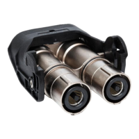
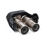
The Amphenol MS & 97B Series connectors are a robust and versatile range of thread and bayonet-coupled components designed to meet stringent operational requirements, particularly those outlined in MIL-C-5015. These connectors are widely used in military and industrial applications where environmental protection and reliability are critical. The MS series and 97B series share identical insert arrangements and similar component parts, with the primary difference being that Amphenol MS series connectors are also qualified to meet the operating requirements of Defence Standard Joint Services Specification JSS50812, issued by the Electronics Components Standardization Organisation (LCSO). The 97B connectors offer a quick mating bayonet coupling with an audible full mating feature, utilizing MIL-C-5015 insert patterns and designed for high shock and vibration environments encountered in geophysical, aerospace, ground support, and shipboard applications.
Technical Specifications:
The connectors are designed with various shell types and classes to accommodate diverse application needs.
Dielectric Strength:
The dielectric strength varies by service rating:
- Inst.: 1000V
- A: 2000V
- D: 2800V
- E: 3500V
- B: 4500V
- C: 7000V
Contact ratings are dependent on contact size:
- Size 16: 13A (Rated Current), 3.46 milliohms (Contact Resistance)
- Size 12: 23A (Rated Current), 1.42 milliohms (Contact Resistance)
- Size 8: 46A (Rated Current), 0.52 milliohms (Contact Resistance)
- Size 4: 80A (Rated Current), 0.26 milliohms (Contact Resistance)
- Size 0: 150A (Rated Current), 0.14 milliohms (Contact Resistance)
Service Rating (Operating Voltage):
Operating voltage specifications vary for DC and AC applications:
- Inst.: 700V (DC), 500V (AC)
- A: 1250V (DC), 900V (AC)
- D: 1750V (DC), 1250V (AC)
- E: 2450V (DC), 1750V (AC)
- B: 4200V (DC), 3000V (AC)
- C: 4200V (DC), 3000V (AC)
Shell Types and Dimensions (MS-3100/MS-4100 Wall Mounting Receptacle):
Dimensions are in mm.
- 10SL: 5/8-24 UNEF (Thread in inches), 1.98 (K), 14.29 (M), 20.62 (O), 18.25 (R), 25.68 (S), 5/8-24 NEF (V Thread in inches)
- 12S: 3/4-20 UNEF, 1.98 (K), 14.29 (M), 20.62 (O), 20.64 (R), 27.76 (S), 11/16-24NEF (V Thread in inches)
- 12: 3/4-20 UNEF, 1.98 (K), 19.05 (M), 20.62 (O), 20.64 (R), 27.76 (S), 11/16-24NEF (V Thread in inches)
- 14S: 7/8-20 UNEF, 1.98 (K), 14.29 (M), 23.82 (O), 23.02 (R), 30.43 (S), 3/4-20 UNEF (V Thread in inches)
- 14: 7/8-20 UNEF, 1.98 (K), 19.05 (M), 23.82 (O), 23.02 (R), 30.43 (S), 3/4-20 UNEF (V Thread in inches)
- 16S: 1-20 UNEF, 1.98 (K), 14.29 (M), 26.97 (O), 24.61 (R), 32.82 (S), 7/8-20 UNEF (V Thread in inches)
- 16: 1-20 UNEF, 3.17 (K), 19.05 (M), 26.97 (O), 24.61 (R), 32.82 (S), 7/8-20 UNEF (V Thread in inches)
- 18: 1 1/8-18 UNEF, 3.17 (K), 19.05 (M), 30.17 (O), 26.99 (R), 35.07 (S), 1-20 UNEF (V Thread in inches)
- 20: 1 1/4-18 UNEF, 3.17 (K), 19.05 (M), 33.32 (O), 29.37 (R), 38.38 (S), 1 1/8-18 NS (V Thread in inches)
- 22: 1 3/8-18 UNEF, 3.17 (K), 19.05 (M), 36.52 (O), 31.75 (R), 41.55 (S), 1 1/4-18 NEF (V Thread in inches)
- 24: 1 1/2-18 UNEF, 3.17 (K), 20.64 (M), 39.67 (O), 34.92 (R), 44.70 (S), 1 3/8-18 NEF (V Thread in inches)
- 28: 1 3/4-18 UNS, 3.17 (K), 20.64 (M), 46.02 (O), 39.69 (R), 51.08 (S), 1 5/8-18 NEF (V Thread in inches)
- 32: 2.00-18 UNS, 3.17 (K), 22.25 (M), 53.0 (O), 44.45 (R), 57.15 (S), 1 7/8-16UN (V Thread in inches)
- 36: 2 1/4-16 UN, 3.17 (K), 22.22 (M), 58.72 (O), 49.21 (R), 63.78 (S), 2 1/16-16UN (V Thread in inches)
- 40: 2 1/2-16 UN, 3.45 (K), 22.22 (M), 62.00 (O), 55.58 (R), 69.85 (S), 2 5/16-16 UN (V Thread in inches)
Shell Types and Dimensions (MS-3101/MS-4101 Cable Connecting Receptacle):
Dimensions are in mm.
- 10SL: 5/8-24 UNEF (A Thread in inches), 5/8-24 NEF (V Thread in inches)
- 12S: 3/4-20 UNEF, 11/16-24 NEF
- 12: 3/4-20 UNEF, 11/16-24 NEF
- 14S: 7/8-20 UNEF, 3/4-20 UNEF
- 14: 7/8-20 UNEF, 3/4-20 UNEF
- 16S: 1-20 UNEF, 7/8-20 UNEF
- 16: 1-20 UNEF, 7/8-20 UNEF
- 18: 1 1/8-18 UNEF, 1-20 UNEF
- 20: 1 1/4-18 UNEF, 1 1/8-18 NS
- 22: 1 3/8-18 UNEF, 1 1/4-18 NEF
- 24: 1 1/2-18 UNEF, 1 3/8-18 NEF
- 28: 1 3/4-18 UNS, 1 5/8-18 NEF
- 32: 2-18 UNS, 1 7/8-16UN
- 36: 2 1/4-16 UN, 2 1/16-16UN
- 40: 2 1/2-16 UN, 2 5/16-16 UN
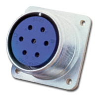
Shell Types and Dimensions (MS-3102/MS-4102 Box Mounting Receptacle):
Dimensions are in mm.
- 10SL: 5/8-24 UNEF (A Thread in inches), 1.98 (K), 30.18 (L), 13.89 (M), 15.87 (N), 18.25 (R), 25.68 (S), 5/8-24 NEF (V Thread in inches)
- 12S: 3/4-20 UNEF, 1.98 (K), 30.18 (L), 14.28 (M), 17.46 (N), 20.64 (R), 28.04 (S), 11/16-24NEF (V Thread in inches)
- 12: 3/4-20 UNEF, 1.98 (K), 30.18 (L), 14.28 (M), 17.46 (N), 20.64 (R), 28.04 (S), 11/16-24NEF (V Thread in inches)
- 14S: 7/8-20 UNEF, 1.98 (K), 30.18 (L), 14.28 (M), 19.05 (N), 23.02 (R), 30.43 (S), 3/4-20 UNEF (V Thread in inches)
- 14: 7/8-20 UNEF, 1.98 (K), 30.18 (L), 19.05 (M), 19.05 (N), 23.02 (R), 30.43 (S), 3/4-20 UNEF (V Thread in inches)
- 16S: 1-20 UNEF, 1.98 (K), 30.18 (L), 19.05 (M), 22.22 (N), 24.61 (R), 32.82 (S), 7/8-20 UNEF (V Thread in inches)
- 16: 1-20 UNEF, 3.17 (K), 30.18 (L), 19.05 (M), 22.22 (N), 24.61 (R), 32.82 (S), 7/8-20 UNEF (V Thread in inches)
- 18: 1 1/8-18 UNEF, 3.17 (K), 49.28 (L), 19.05 (M), 25.40 (N), 26.99 (R), 35.07 (S), 1-20 UNEF (V Thread in inches)
- 20: 1 1/4-18 UNEF, 3.17 (K), 49.28 (L), 19.05 (M), 28.57 (N), 29.37 (R), 38.38 (S), 1 1/8-18 NS (V Thread in inches)
- 22: 1 3/8-18 UNEF, 3.17 (K), 49.28 (L), 19.05 (M), 31.75 (N), 31.75 (R), 41.55 (S), 1 1/4-18 NEF (V Thread in inches)
- 24: 1 1/2-18 UNEF, 3.17 (K), 49.28 (L), 20.64 (M), 34.92 (N), 34.92 (R), 44.70 (S), 1 3/8-18 NEF (V Thread in inches)
- 28: 1 3/4-18 UNS, 3.17 (K), 49.28 (L), 20.64 (M), 39.69 (N), 39.69 (R), 51.08 (S), 1 5/8-18 NEF (V Thread in inches)
- 32: 2-18 UNS, 3.17 (K), 49.28 (L), 22.22 (M), 44.45 (N), 44.45 (R), 57.15 (S), 1 7/8-16UN (V Thread in inches)
- 36: 2 1/4-16 UN, 3.17 (K), 49.28 (L), 22.22 (M), 49.21 (N), 49.21 (R), 63.78 (S), 2 1/16-16UN (V Thread in inches)
- 40: 2 1/2-16 UN, 3.45 (K), 49.28 (L), 22.22 (M), 55.58 (N), 55.58 (R), 69.85 (S), 2 5/16-16 UN (V Thread in inches)
Shell Types and Dimensions (MS-3106/MS-4106 Straight Plug):
Dimensions are in mm.
- 10SL: 5/8-24 UNEF (A Thread in inches), 19.05 (Q max), 5/8-24 NEF (V Thread in inches)
- 12S: 3/4-20 UNEF, 19.84 (Q max), 11/16-24 NEF (V Thread in inches)
- 12: 3/4-20 UNEF, 19.84 (Q max), 11/16-24 NEF (V Thread in inches)
- 14S: 7/8-20 UNEF, 22.22 (Q max), 3/4-20 UNEF (V Thread in inches)
- 14: 7/8-20 UNEF, 22.22 (Q max), 3/4-20 UNEF (V Thread in inches)
- 16S: 1-20 UNEF, 25.40 (Q max), 7/8-20 UNEF (V Thread in inches)
- 16: 1-20 UNEF, 25.40 (Q max), 7/8-20 UNEF (V Thread in inches)
- 18: 1 1/8-18 UNEF, 28.57 (Q max), 1-20 UNEF (V Thread in inches)
- 20: 1 1/4-18 UNEF, 31.75 (Q max), 1 1/8-18 NS (V Thread in inches)
- 22: 1 3/8-18 UNEF, 34.92 (Q max), 1 1/4-18 NEF (V Thread in inches)
- 24: 1 1/2-18 UNEF, 38.10 (Q max), 1 3/8-18 NEF (V Thread in inches)
- 28: 1 3/4-18 UNS, 44.45 (Q max), 1 5/8-18 NEF (V Thread in inches)
- 32: 2-18 UNS, 51.75 (Q max), 1 7/8-16UN (V Thread in inches)
- 36: 2 1/4-16 UN, 57.15 (Q max), 2 1/16-16UN (V Thread in inches)
- 40: 2 1/2-16 UN, 63.50 (Q max), 2 5/16-16 UN (V Thread in inches)
Shell Types and Dimensions (MS-3108/MS-4108 Right Angle Plug):
Dimensions are in mm.
- 10SL: 5/8-24 UNEF (A Thread in inches), 19.05 (Q max), 5/8-24 NEF (V Thread in inches)
- 12S: 3/4-20 UNEF, 19.84 (Q max), 11/16-24 NEF (V Thread in inches)
- 12: 3/4-20 UNEF, 19.84 (Q max), 11/16-24 NEF (V Thread in inches)
- 14S: 7/8-20 UNEF, 22.22 (Q max), 3/4-20 UNEF (V Thread in inches)
- 14: 7/8-20 UNEF, 22.22 (Q max), 3/4-20 UNEF (V Thread in inches)
- 16S: 1-20 UNEF, 25.40 (Q max), 7/8-20 UNEF (V Thread in inches)
- 16: 1-20 UNEF, 25.40 (Q max), 7/8-20 UNEF (V Thread in inches)
- 18: 1 1/8-18 UNEF, 28.57 (Q max), 1-20 UNEF (V Thread in inches)
- 20: 1 1/4-18 UNEF, 31.75 (Q max), 1 1/8-18 NS (V Thread in inches)
- 22: 1 3/8-18 UNEF, 34.92 (Q max), 1 1/4-18 NEF (V Thread in inches)
- 24: 1 1/2-18 UNEF, 38.10 (Q max), 1 3/8-18 NEF (V Thread in inches)
- 28: 1 3/4-18 UNS, 44.45 (Q max), 1 5/8-18 NEF (V Thread in inches)
- 32: 2-18 UNS, 51.75 (Q max), 1 29/32-18 NS (V Thread in inches)
- 36: 2 1/4-16 NS, 57.15 (Q max), 2 1/16-20 UNS (V Thread in inches)
- 40: 2 1/2-16 UN, 63.50 (Q max), 2 5/16-16 UN (V Thread in inches)
Usage Features:
General Description:
These electrical connectors are designed to be interchangeable and meet operating characteristics determined by U.S. Military Specifications. They are revised periodically to incorporate performance requirements driven by design advances and more stringent requirements of allied equipment. The various designations of MS and 97B connectors use different requirements of MIL-C-5015.
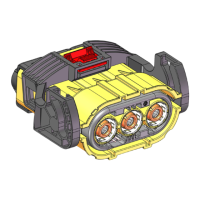
Shell Construction:
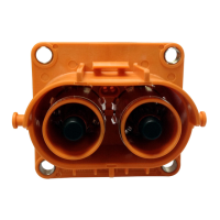
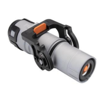
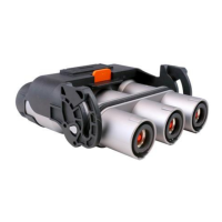
Shells are available in solid back shell (A) and environmental resistant (E, F, & R) designs. Environmental resistant connectors provide a moisture barrier and assure a positive seal. Shell styles include straight plugs (3106), box receptacles (3102), cable receptacles (3101), and angle plugs (3108). Shell hardware is manufactured from aluminum alloy and cadmium plated with olive drab chromate finish. This finish provides excellent conductivity, is non-reflecting, and corrosion resistant. Black anodised finish and cadmium-free zinc plating with olive drab chromate finish are also available.
Pin and socket contacts are made of brass and generally silver plated. Gold plating is also available. For details, contact the factory. These contacts are suitable for solder or crimp termination. Special arrangements of contacts for pre-mating and pre-earth are also available.
Inserts and Grommet:
Synthetic inserts and grommet are manufactured according to MIL-R-3065, offering high dielectric strength and are resistant to oils, gasoline, and low temperature. DAP is dimensionally stable, has high resistance, and high insulation resistance under both humidity and thermal stress. Plugs are available in A, F, and R types. Receptacles are available in A, E, F and R types.
Solid Back Shell:
Intended for general service usage to provide convenient means of connecting and disconnecting electrical circuits in industrial and military applications.
Environmental Resisting:
Intended for use where the connector will be subject to heavy condensation and rapid changes in temperature or pressure and/or where the connector is subjected to high vibratory conditions.
- E: Environmental resisting with grommet seal and strain relief backshell (except for 3100 type).
- F: Environmental resisting with grommet seal, strain relief backshell and front gasket seal for plug type.
- R: Environmental resisting with grommet seal, shorter and lightweight.
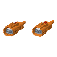
Features for 97B Reverse Bayonet Coupling Connectors with MIL-C-5015 Insert Patterns:
- Quick positive coupling
- Audible and tactile indication of full coupling
- Waterproof
- No lockwiring required
- High shock and vibration capabilities
- Insert available in Neoprene material (alternate inserts materials available upon request)
- Operating temperature range with Neoprene inserts: -55°C to +125°C
- Available in both crimp and solder terminations
- Contacts available in gold and silver plating
- Numerous finishes available
- Zinc alloy plating (cadmium free) available
- Rugged construction; aluminum or stainless steel components
- Intermateable with existing VG95234 connectors
- 500 couplings minimum
The part number system follows a specific format to identify the connector's characteristics.
- Series Designation: MS (Threaded version), 97B (Bayonet version)
- Contact Type: P (Pin contacts), S (Socket contacts)
- Shell Size: 10SL, 12S, 12, 14S, 14, 16S, 16, 18, 20, 22, 24, 28, 32, 36, 40
- Shell Finish: Standard (Cadmium plating with olive drab chromate finish), Alternate finishes (Cadmium free zinc-cobalt plating with olive drab chromate finish-622, Zinc-cobalt free zinc-cobalt plating with black finish-623, Electroless Nickel plating-624, 4.608, Black Anodized).
- Connector Class: A (Solid backshell), F (Environmental resisting with grommet seal and strain relief backshell), R (Environmental resisting with grommet seal, shorter and lightweight), PG (Environmental resisting with grommet seal, straight PG threaded backshells), PQ (Environmental resisting with grommet seal, PG threaded backshells for heat shrinkable end shells), EGM (Backshell with metal ferrule for shielded cable), PHM (Backshell without metal ferrule for unshielded cable).
For 97B - Connector Modification:
- F/A: Less grommet & backshell
- G/LC: Less contacts
- 563: Gold plated contacts
- T 00: Metric threads in flange holes
- 97 BB: Bayonet version with Steel wear pin (for receptacle connector)
- 97 L: Plug connector with grounding finger
- HD: Heavy duty coupling ring
Maintenance Features:
Contacts for MS/97B connectors are machined from copper alloys and silver plated for maximum corrosion resistance, with a minimum millivolt drop and a maximum current carrying capacity. Size 16 and 12 socket contacts feature a closed entry design. Gold plated contacts are also available. Solder contacts are not sold as separate items.
When proprietary crimp contacts are used instead of standard MS approved solder contacts, specific application tools are recommended.
- Crimping Tool: M22520/1-01
- Positioner/Turret: Use Daniels Turret TH29-1 or Astro Tool Co. Turret 616266. For appropriate crimp tool and positioner, refer to Pico Crimping Tool Co.
Protective Caps:
Protective caps are available for both MS and 97B series connectors.
- MS-25043 (for receptacles): Has internal threads and includes a gasket to form a watertight seal. Available with nylon cord. Standard plating is Cadmium, with alternative finishes available. Standard is straight knurling, with diamond knurling available.
- MS-25042 (for plugs): Has external threads and is used on all plugs with a coupling ring.
- 97B-25042 (for plugs): Similar to MS-25042 but for 97B series.
- 97B-25043 (for receptacles): Similar to MS-25043 but for 97B series.
Dummy Receptacle (MS-3105):
Used to protect unused plugs. The dash number indicates the shell size.
Other Accessories:
- Neoprene Sleeve (MS-3420): Rubber bushing that protects wire bundles and unjacketed cables from possible damage by cable clamp.
- Plain Flat Gasket (MS-101000 series): For MS and 97B flange mounted receptacles.
- Cable Clamp (MS-3057): Used with MS-3420 sleeves.
- Heat Shrink Boot Adaptor (G).
- PG Adaptor.
- EGM/PHM Backshell Accessories.