5
OPERATION
Note: All function operations described hereafter are via
the stationary “Yellow” probe for positive (+) polarity
and the attached “Black” probe for Ground reference (-),
or otherwise specified.
Automatic Operation
The tester automatically turns on when you place the
probes across a complete circuit. The tester selects
continuity or DC or AC voltage mode based on the
resistance or voltage between the probes. The tester
automatically turns off when you remove the probes
from the complete circuit.
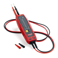
Voltage Measurement (Refer to Figs 1, 2 and 4)
Connect test leads across the source or load under
measurement, the LED turned on at between 70% and
100% of their rated voltages.
DC Voltage: 600V maximum
AC Voltage: 600V rms maximum, 45 to 66Hz
Continuity Testing (Refer to Figs 3)
Turn off circuit power before testing. Beeper indicates
shorts lasting 1ms or longer. Short circuit=0-85KW
SPECIFICATION
Function Range Accuracy
AC voltage (V) 24,120,208,240, 277,
480,600
-30% to 0% of
reading
DC voltage (V) 6,12,24,36,48, 110,220 -30% to 0% of
reading
Continuity Test: Audible threshold 0-85kW, Continuity
beeper 2KHz
Maximum Voltage Between any Terminal and Earth
Ground: 600V DC; 600V AC rms, Overvoltage Category III