EasyManua.ls Logo

Amtrol CH4202 - User Manual

Amtrol CH4202
12 pages
Print Icon
To Next Page IconTo Next Page
Loading...
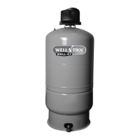
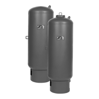
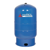
Pre-pressurized Water System Well Tanks
Réservoirs de puits de système d’eau à pressurisation initiale
Tanques hidroneumáticos prepresurizados para sistemas de agua
Models Include: Stand
Les modèles incluent: À support
Los modelos incluyen: Base
WARNING: REVIEW ALL GENERAL SAFETY AND PRODUCT INFORMATION ON PAGE 2 PRIOR TO INSTALLATION.
AVERTISSEMENT: EXAMINER TOUTES LES INFORMATIONS GÉNÉRALES DE SÉCURITÉ ET DE PRODUIT DE
LA PAGE 5 AVANT L’INSTALLATION.
ADVERTENCIA: ANTES DE INSTALAR, REPASE TODA LA INFORMACIÓN GENERAL DE SEGURIDAD Y DEL
PRODUCTO QUE SE ENCUENTRA EN LA PÁGINA 8.
Your well tank by AMTROL has been carefully assembled and factory tested. To enjoy the full service your well tank can provide,
you should read and follow all of the instructions in this manual. When all installation steps have been completed, make sure you also
follow the enclosed post-installation and start-up checklists before using your AMTROL product. You should also read carefully the
sections describing proper product maintenance, and follow the required procedures as you use your well tank. Return this booklet
to its original envelope, and keep it with the well tank. This manual may become out-of-date by later amendments. Check our web
site, www.amtrol.com, or ask your AMTROL supplier for any updates relating to your product. This product comes with a limited
five (5) year warranty, see AMTROL Limited Warranty for details. Our goal is to ensure you are fully satisfied with your new well
tank. If any questions or concerns arise, call Technical Service at 401-535-1216.
Ce réservoir de puits AMTROL a été assemblé et testé à l’usine avec soin. Pour utiliser toute sa fonctionnalité, veuillez lire et suivre
toutes les instructions de ce manuel. Après avoir effectué toutes les étapes de l’installation, il faut s’assurer de suivre aussi les listes
ci-jointes de contrôle après installation et de démarrage avant d’utiliser ce produit AMTROL. Lire aussi avec soin les sections crivant
la maintenance appropriée à ce produit et suivre les procédures requises pour l’utilisation du réservoir de puits. Remettre en place
ce livret dans sa pochette d’origine et le conserver avec le réservoir. Ce manuel peut être l’objet de révisions ultérieures. Consulter
notre site Internet à www.amtrol.com ou demander au fournisseur AMTROL les mises à jour concernant ce produit. Ce produit est
vendu avec une garantie limitée de cinq (5) ans. Voir la garantie limitée d’AMTROL pour de plus amples informations. Notre
but est d’assurer l’entière satisfaction pour ce nouveau réservoir de puits. Pour toute question ou problème, contacter le Service
technique au 401-535-1216.
Su tanque hidroneumático fabricado por AMTROL ha sido cuidadosamente ensamblado y probado en fábrica. Para que pueda
disfrutar por completo el servicio que su tanque hidroneumático le puede proveer, le recomendamos que lea y siga todas las
instrucciones que hay en este manual. Cuando complete todos los pasos de instalación, cerciórese de haber seguido también las
listas de verificación pos instalación y de puesta en marcha, antes de usar su producto AMTROL. Asimismo, le recomendamos que lea
cuidadosamente las secciones que describen el mantenimiento apropiado del producto, y que al usar su tanque hidroneumático siga
los procedimientos requeridos. Vuelva a colocar este folleto en su sobre original yngalo junto a su tanque. Este manual puede
quedar desactualizado por enmiendas posteriores, por lo que le recomendamos que verifique en nuestro sitio de Web, www.amtrol.
com, o que le pregunte a su proveedor de productos AMTROL, si hay alguna actualización para su producto. Este producto tiene
una garantía limitada de cinco (5) años; para mayor información remitirse a la Garantía Limitada de AMTROL. Nuestra meta
es asegurar su completa satisfacción con su nuevo tanque hidroneumático. Si tiene alguna pregunta o inquietud, llame al Servicio
Técnico al 401-535-1216
THIS IS THE SAFETY ALERT SYMBOL. IT IS USED TO ALERT YOU TO POTENTIAL PERSONAL INJURY AND
OTHER HAZARDS. OBEY ALL SAFETY MESSAGES THAT FOLLOW THIS SYMBOL TO REDUCE THE RISK OF
POSSIBLE INJURY AS WELL AS PROPERTY DAMAGE.
VOICI LE SYMBOLE D’ALERTE DE SÉCURITÉ. IL EST UTILISÉ POUR SIGNALER LES RISQUES D’ACCIDENT OU AUTRES
DANGERS. IL FAUT RESPECTER TOUS LES MESSAGES DE SÉCURITÉ QUI SUIVENT CE SYMBOLE AFIN DE RÉDUIRE LES
RISQUES POTENTIELS DE BLESSURE OU DE DOMMAGE MATÉRIEL.
ESTE ES EL SÍMBOLO DE ALERTA DE SEGURIDAD. SE USA PARA ALERTARLE DE POSIBLES LESIONES Y OTROS
PELIGROS. PARA REDUCIR EL RIESGO LESIONES, ASÍ COMO DE DAÑOS MATERIALES, OBEDEZCA TODOS LOS
MENSAJES DE SEGURIDAD QUE ACOMPAÑAN A ESTE SÍMBOLO.
INSTALLATION, OPERATION & MAINTENANCE INSTRUCTIONS
D’INSTALLATION, D’OPÉRATION ET DE MAINTENANCE INSTRUCTIONS
INSTRUCCIONES DE INSTALACIÓN, OPERACIÓN Y MANTENIMIENTO
Precharged Well Tanks / 125 PSIG Rating
Question and Answer IconNeed help?

Do you have a question about the Amtrol CH4202 and is the answer not in the manual?

Overview

This document provides installation, operation, and maintenance instructions for AMTROL Precharged Well Tanks, rated for 125 PSIG. These tanks are designed for use in pre-pressurized water systems. The manual covers models that include a stand or base.

Function Description:

AMTROL Precharged Well Tanks are integral components of water well systems, designed to store pressurized water and maintain system pressure, thereby reducing pump cycling and extending pump life. The tank's pre-charge pressure works in conjunction with the pressure switch to ensure efficient operation of the well pump. When the pump fills the tank, the air pre-charge compresses, storing energy. When water is drawn from the system, the compressed air pushes water out, delaying the need for the pump to turn on. This mechanism helps to stabilize water pressure, reduce wear and tear on the pump, and provide a consistent water supply.

Important Technical Specifications:

  • Maximum Working Pressure: All well tanks are air tested to 125 PSIG (8.8 kg/cm²), which is the maximum working pressure for the well tank line.
  • Relief Valve Requirement: A relief valve with a maximum relief pressure of 100 PSIG (7.03 kg/cm²) must be installed in the system. This valve must be capable of discharging the rated capacity of the pump at the maximum system pressure.
  • Standard Pre-charge Pressure (Factory Setting): All well tanks are shipped with a standard pre-charge of 38 PSIG.
  • Recommended Pre-charge Adjustment: The pre-charge pressure should be set to 2 PSIG below the pressure switch pump cut-in setting. For example, if the pressure switch setting is 30/50 PSIG, the tank's pre-charge should be adjusted to 28 PSIG.
  • Pipe Sizing for Manifold Installations:
    • 1 inch pipe: 17 GPM
    • 1 1/4 inch pipe: 30 GPM
    • 1 1/2 inch pipe: 40 GPM
    • 2 inch pipe: 60 GPM
  • Temperature Limits: Install or store where the tank will not be exposed to temperatures below freezing or above 100°F (38°C). Water freezing in the system will break it. Do not attempt to treat water over 100°F.

Usage Features:

  • Professional Installation: The product must be installed and maintained by a licensed professional. All applicable local and state codes, or the current editions of the National Plumbing Code and National Electric Code, must be followed.
  • Location: The well tank should be installed as close as possible to the pressure switch to minimize friction loss, pressure switch bouncing, and elevation differences.
  • System Connection:
    • Place the well tank in its final desired location and ensure it is level.
    • Do not reduce the pipe size from the pump to the well tank to eliminate friction loss.
  • Pre-charge Adjustment (Prior to Installation):
    1. Remove the protective air valve cap.
    2. Check the pre-charge pressure (it should be +/- 10% of the factory setting).
    3. Release or add air as necessary to set the pre-charge pressure 2 PSIG below the pressure switch pump cut-in setting.
    4. Replace the protective air valve cap.
  • Fine Tuning Procedures (After Start-up):
    1. Fill the system and well tank until the pump cuts off.
    2. Open one or more fixtures to drain the well tank.
    3. If there is a momentary pause in water flow between the tank emptying and the pump starting, adjust the pump cut-in setting clockwise slightly (refer to Figure 2 in the manual for pressure adjustment).
    4. Close fixtures and refill the well tank to pump cut off, noting the fill time.
    5. Open fixtures again to check if the pause in water flow is eliminated. If not, continue adjusting the pressure switch.
  • Pre-charge Adjustment (After Installation):
    1. Drain all water from the tank.
    2. Check the pre-charge pressure in the well tank.
    3. Release or add air as necessary to set the pre-charge pressure 2 PSIG below the pressure switch pump cut-in setting.
  • Safety Alert Symbol: The manual uses a safety alert symbol to warn of potential personal injury and other hazards. All safety messages following this symbol must be obeyed to reduce the risk of injury and property damage.
  • Bacterial Growth: As with all plumbing products and water storage vessels, bacteria can grow in the well tank, especially during non-use. Consult a local plumbing official for disinfection steps.
  • Water Quality: Water quality significantly influences the product's life. Test for corrosive elements, acidity, total solids, chlorine, and other contaminants, and treat water appropriately to ensure satisfactory performance and prevent premature failure.

Maintenance Features:

  • Periodic Inspection: A licensed professional must periodically inspect and service the unit to minimize the risk of corrosion, failure, bursting, leaking, or flooding.
  • Drip Pan Installation: If leaking or flooding can cause property damage, a drip pan connected to an adequate drain must be installed and kept clear at all times.
  • Corrosion and Damage: Do not adjust or add pressure to a tank that is corroded or damaged, or has diminished integrity, as this can cause it to burst or explode.
  • Loss of Air/Reduced Pump Cycle Time: Do not adjust the pre-charge pressure if there has been a loss of air or a reduction in pump cycle time, as this may indicate internal corrosion. Re-pressurization or additional pressure in such cases could lead to rupture or explosion.
  • Qualified Professionals: Only qualified professionals should check, adjust, or re-charge the pre-charge of tanks.
  • Lead-Free Solder: Use only lead-free solder and flux for all sweat-solder connections, as required by state and federal codes.
  • Grounding: Properly ground the system to conform with all governing codes and ordinances to minimize the risk of electric shock.
  • Warranty: The product comes with a limited five (5) year warranty. The warranty is for the original purchaser or first user and is not transferable. It covers defects in material and workmanship at the time of manufacture. The warranty does not cover labor costs, additional parts, shipping charges, property damage, or issues arising from abuse (including freezing), improper handling, storage, installation, operation, maintenance, or alteration of the product. Warranty claims must be made within 30 days of failure and no more than 30 days after the expiration of the applicable warranty period. AMTROL may require proof of purchase, ownership, product model and serial number, and evidence of proper installation and maintenance. AMTROL reserves the right to repair or supply new or used replacement parts or products. Replacement parts or products carry only the balance of the original warranty. Implied warranties of merchantability and fitness for a particular purpose are specifically disclaimed. Remedies are limited to the price paid for the product, and AMTROL is not liable for special, indirect, incidental, or consequential damages.

This manual emphasizes the importance of reading and following all instructions carefully to ensure safe use and proper care of the AMTROL well tank. Failure to comply with warnings can result in serious injury, property damage, and void the warranty. For any questions or concerns, technical service can be contacted at 401-535-1216. Current product manuals are available on www.amtrol.com.

Amtrol CH4202 Specifications

General IconGeneral
BrandAmtrol
ModelCH4202
CategoryWater Heater
LanguageEnglish

Related product manuals