Connection and Wiring
6
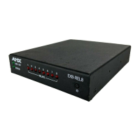
AXB-REL8 Axcess Relay Controller
Testing the installation
1. Check AXlink status LED - it should blink once per second (see Specifications table for
AXlink status LED).
2. Relay LED lights, but source does not activate:
3. Check wiring continuity.
4. Check jumpers used for shared commons.
5. Check cable and source against supplied documentation.
6. Check operational status of interface or source.
Rack-Mounting the AXB-REL8 (optional)
To rack-mount the AXB-REL8 into the optional AC-RK Accessory Rack Kit:
1. Remove any connected relay and AXlink connectors from the rear panel.
2. Remove the two screws on the front panel of the AXB-REL8.
3. Remove the front panel and the space bracket behind the panel.
4. Place the unit in the appropriate opening in the AC-RK.
5. Place the front panel of the AXB-REL8 on the front of the rack, over the unit.
6. Fasten the front panel to the rack and to the unit with the two screws you removed.
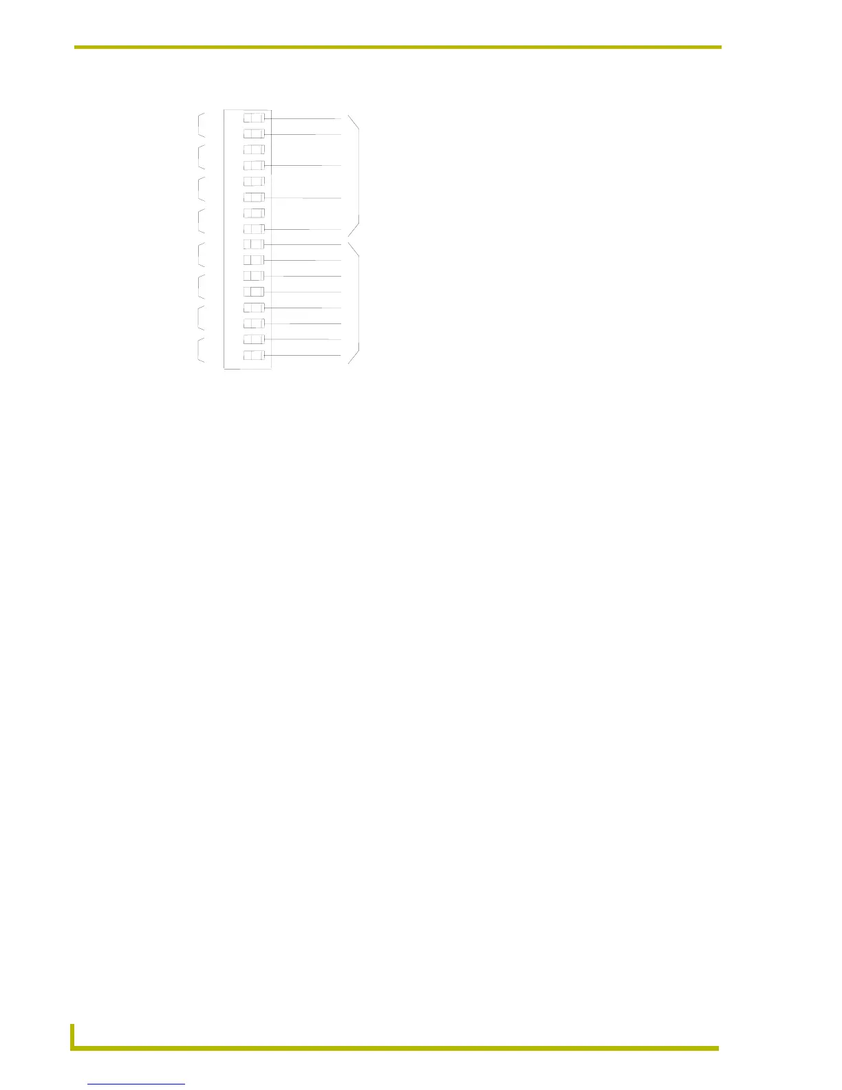
FIG. 5 Relay wiring diagram
4
3
2
1
B
B
RELAYS SHARING A COMMON
Jumper "A" pins with tab strip
RELAYS WITH DISCRETE COMMONS
Wire commons individually