Product Overview and General Specifications
16
Hardware Reference Manual – Enova DGX 100 Series Digital Media Switchers
Front View
The enclosure, which is the structural basis of an Enova DGX Switcher, can be controlled using an external controller, control
software, the integrated NetLinx NX Central Control Processor’s System Configuration interface, or standard front control panel.
For additional information on control options, see page 33.
Power Indicator LED on Front of Enclosure
The Power Indicator LED on the front of the enclosure indicates the status of the redundant power system within an Enova DGX
Switcher as follows:
Enova DGX 800/1600/3200
Green – both power supplies are powered on
Red – one of the power supplies is not receiving power or has failed
Off – neither power supply is receiving power
Enova DGX 6400
Green – all four power supplies are powered on
Constant Red – one of the power supplies is not receiving power or has failed
Flashing Red – two (or three) of the power supplies are not receiving power or have failed
Flashing Green – the system’s input/output boards are being upgraded*
Off – none of the power supplies is receiving power
IMPORTANT: If two or more power supplies in the Enova DGX 6400 are not receiving power, the CPU and the control panel will
continue to operate. However, input and output boards will become inoperable and the system will not send or receive signals until at
least three power supplies resume functional status.
* The LED’s response to power functions supersedes the upgrade function.
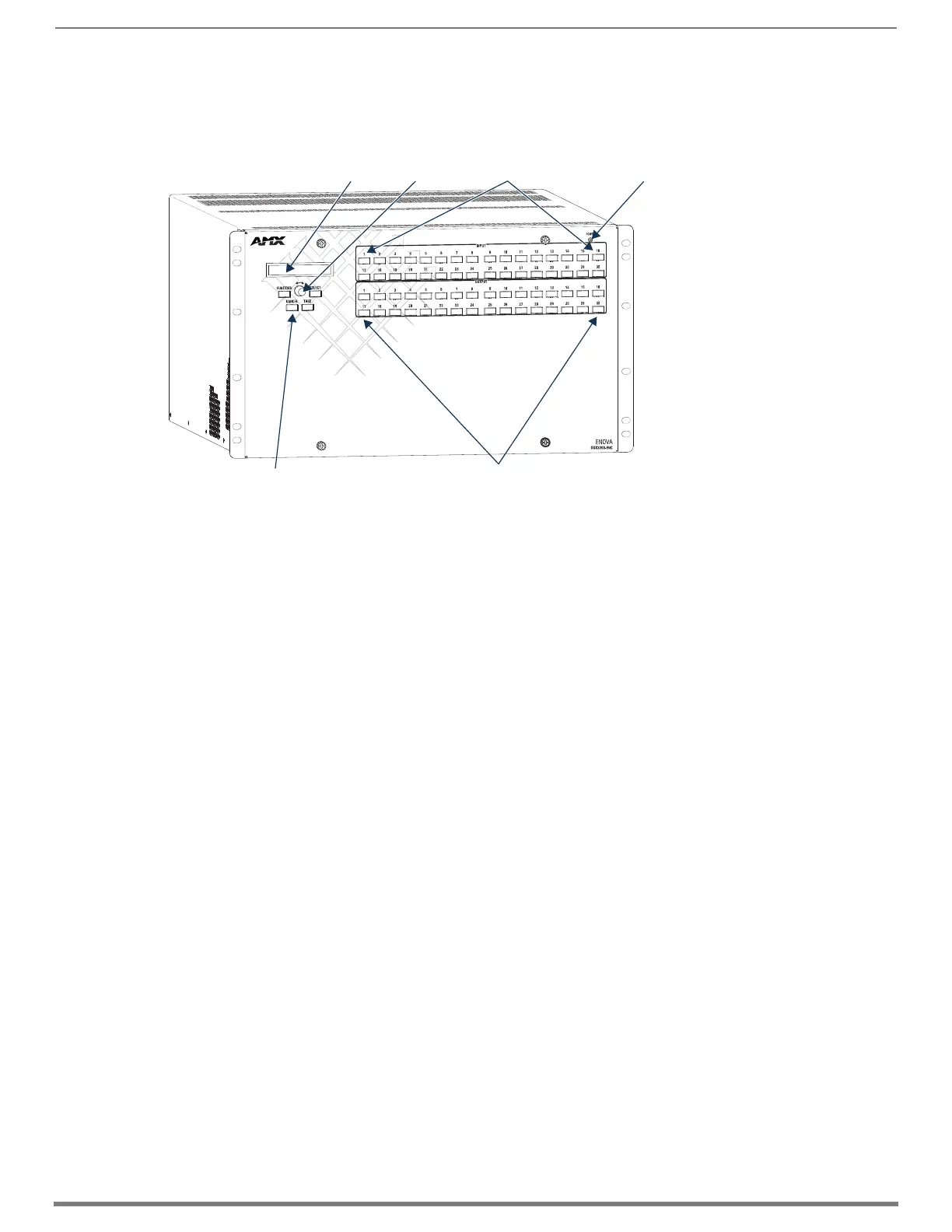
FIG. 2
Front view of an Enova DGX 3200 enclosure
LCD Power Indicator LEDControl Dial
Control Keys
Output Keys
Input Keys

 Loading...