Installation
18
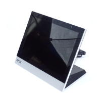
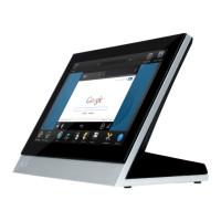
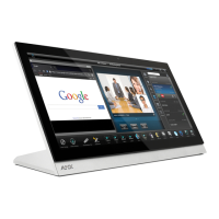
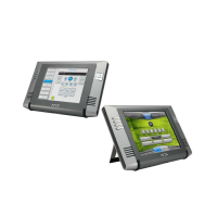
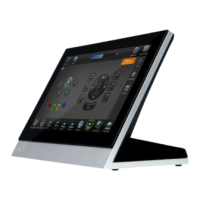
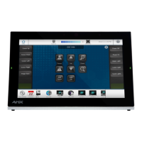
MXD/T-1900L-PAN 19.4" Modero X Series® Panoramic Touch Panels
To install the back box:
1. Prepare the area by removing any screws or nails from the drywall before beginning the cutout process.
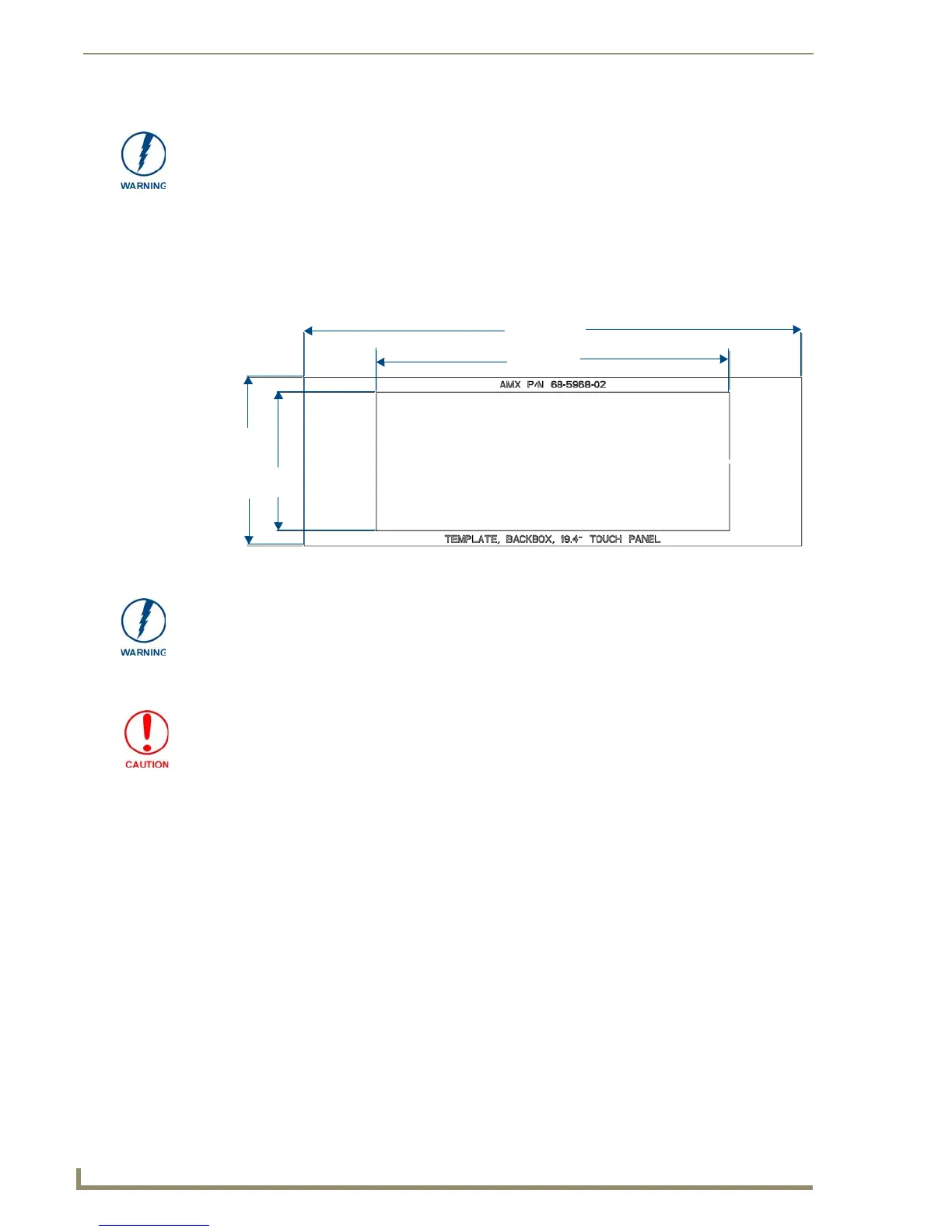
2. Since the cutout for the back box is off-center from the edges of the touch panel, use the MXD-1900L-
PAN Installation Template (68-5968-02) to ensure proper placement (FIG. 17).
3. Cut out the surface for the back box.
4. Thread the incoming power, Ethernet, and Micro-USB wiring (if Micro-USB access is desired) from their
terminal locations through the surface opening (FIG. 18 and FIG. 19). Leave enough slack in the wiring
to accommodate any re-positioning of the panel.
5. Remove any knockouts as needed on either long dimension of the back box (FIG. 18 and FIG. 19) to
facilitate incoming wiring and pull the wiring through the resultant holes.
6. Push the back box into the wall opening. Insure that the locking tabs lie flush against the back box.
The maximum recommended torque to screw in the locking tabs on the plastic back
box is 5 IN-LB [56 N-CM]. Applying excessive torque while tightening the tab screws,
such as with powered screwdrivers, can strip out the locking tabs or damage the
plastic back box.
FIG. 17 MXD-1900L-PAN Template
20.433"
519.00 mm)
6.89"
175.00 mm)
14.50"
368.30 mm)
5.69"
144.50 mm)
Using the included template to select the final placement of the back box is highly
recommended. The outside edges of the template are the same dimensions as the
touch panel, which allows you to troubleshoot possible conflicts with wall edges,
doors, and other potential obstacles.
Making sure that the actual cutout opening is slightly smaller than the provided
dimensions is highly recommended. This action provides the installer with a margin
for error if the opening needs to be expanded. Too little wall material removed is
always better than too much.
 Loading...