Installation
22
MXD/T-1900L-PAN 19.4" Modero X Series® Panoramic Touch Panels
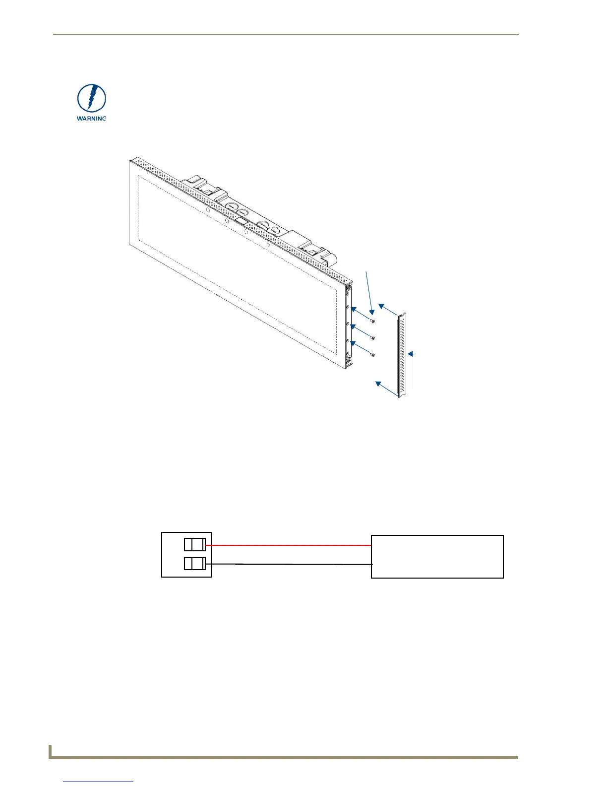
11. Use the six provided screws, three at each end, to secure the touch panel to the back box (FIG. 22 and
FIG. 23). Use only the provided screws, as other screws may damage the touch panel.
12. Snap the decorative side covers (FIG. 23) onto each end of the touch panel.
13. Reconnect the terminal Ethernet and USB to their respective locations on either the Ethernet port or
NetLinx Master.
Wiring a Power Connection
To use the 2-pin 3.5 mm captive wire connector with a 12 VDC-compliant power supply, the incoming PWR
and GND wires from the external source must be connected to their corresponding locations on the connector
(FIG. 24). The connector uses locking screws to insure a connection to the device, so make sure to insert and
tighten the screws before applying power.
1. Insert the PWR and GND wires on the terminal end of the 2-pin 3.5 mm captive wire cable. Match the
wiring locations of the +/- on both the power supply and the terminal connector.
2. Tighten the clamp to secure the two wires. Do not tighten the screws excessively; doing so may strip the
threads and damage the connector.
3. Verify the connection of the 2-pin 3.5 mm captive wire to the external 12 VDC-compliant power supply
and apply power.
When installing the panel, do NOT press on or near the center of the panel. Too
much stress at the center may damage the touch screen surface. When installing the
panel, pressure should be applied toward the ends of the panel ONLY.
FIG. 23 MXD-1900L-PAN side cover installation (Landscape)
FIG. 24 NetLinx power connector wiring diagram
MXD-1900L-PAN
Screws (3)
Side cover
PWR +
GND -
To the Touch Panel
Power Supply
 Loading...