Installation
20
MXD/T-1900L-PAN 19.4" Modero X Series® Panoramic Touch Panels
The back box is clear to allow visual confirmation that the tabs have been extended and are gripping the
wall, as well as in assisting with removal if necessary.
8. For additional strength, #4 mounting screws (not included) may be secured through circular holes located
at the left and right sides of the MXD-1900L-PAN (FIG. 18 and FIG. 19). In order to prevent damage to
the touch panel, make sure that these are flush with the back box.
9. Insert each connector into its corresponding location along the back of the device (FIG. 20).
10. Test the incoming wiring by attaching the panel connections to their terminal locations and applying
power. Verify that the panel is receiving power and functioning properly to prevent repetition of the
installation.
Insert the four temporary mounting posts of the panel (FIG. 21 and FIG. 22) into the openings on the back box
and slide the panel onto the back box. This will temporarily hold the panel during the rest of the installation.
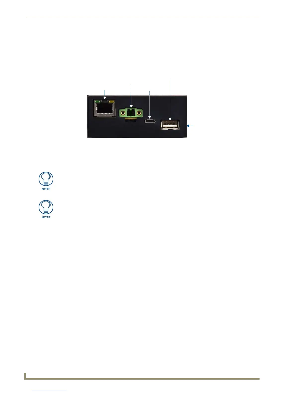
FIG. 20 MXD-1900L-PAN rear connectors (front view)
Ethernet 10/100
Port
Micro-USB
Port
USB Port
12 VDC
Power Port
Limited Access
USB Port
Do not disconnect the connectors from the touch panel. The unit must be installed
with the attached connectors before being inserted into the drywall.
Configurations that use the limited access USB port on the side of the connector box
may require a right angle mating connector (not included) for connection to the
device.
 Loading...