UG-207 Evaluation Board User Guide
EVALUATION BOARD LAYOUT
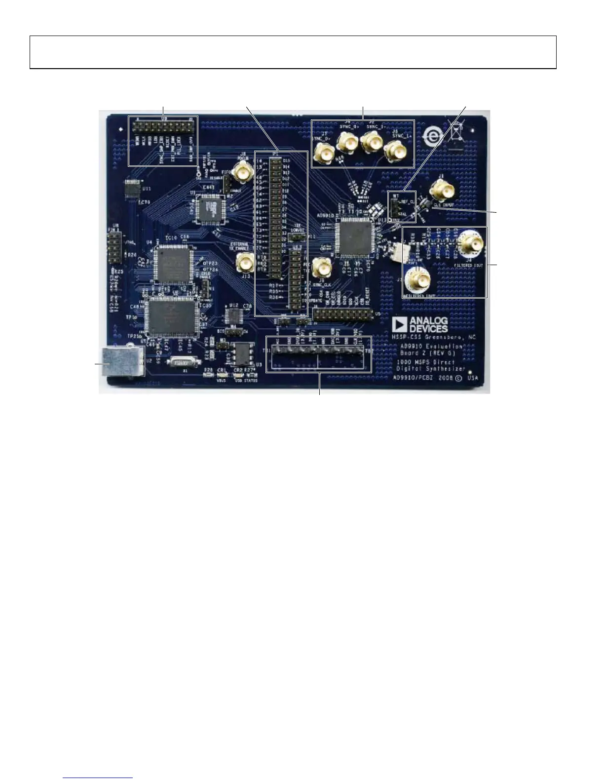
07481-002
MULTIDEVICE
SYCNHRONOUS CONTROL
CLOCK MODE
SELECT
REF
CLOCK
INPUT
DAC
OUTPUT
POWER SUPPLY
CONNECTIONS
MANUAL I/O
CONTROL HEADERS
STATUS PINS
USB PORT
Figure 2. AD9910 PCB Evaluation Board
Manual I/O Control Headers
These pins provide the communication interface for the
AD9910 when the part is under the command of an external
controller (see Table 3 for correct jumper settings).
Multidevice Synchronous Control
These connections set up the AD9910 for multidevice
synchronous operation.
DAC Output
These connections represent the filtered or unfiltered (default)
output of the DAC.
Clock Mode Select
This connection controls whether the reference clock source is a
20 MHz to 30 MHz crystal, or is from an external signal generator.
A 25 MHz crystal is provided on the underside of the AD9910
evaluation board.
Ref Clock Input
This is the input for the external reference clock signal.
Power Supply Connections
These two connectors, TB1 and TB2, provide all necessary
supply voltages needed by the AD9910 and the evaluation board
(see Table 2).
USB Port
When the part is under PC control (default mode), the evaluation
board communicates with the AD9910 via this port.
Rev. A | Page 4 of 16
 Loading...


