Preliminary Technical
Data
Rev. PrA | Page 21 of 82
Figure 24. ADRV9025 DPD Dynamics in DPD Mode 2
Observation receiver Low Power Threshold
The observation receiver low power threshold can be used to compare observation samples against the threshold specified by
adi_adrv9025_DpdTrackingConfig_t.minAvgSignalLevelOrx in linear scale, to determine if a DPD update needs to be applied. This
can help avoid DPD updates when the signal level is low and, consequently, the signal to noise ratio of the observed samples is
poor. If the rms power of the DPD capture samples is greater than the observation channel low power threshold, an update will
be applied to the appropriate DPD model if the Tx low power threshold condition described in the previous section is also
satisfied. Table 4 captures the various conditions related to the power levels and updates of transmitter and observation receiver
captured samples.
Table 4. DPD Update Criteria Based on the Signal Level of Captured Samples
DPD Capture Samples RMS power
condition
DPD captured Tx samples >
adi_adrv9025_DpdTrackingConfig_t.
minAvgSignalLevel
DPD captured Tx samples <
adi_adrv9025_DpdTrackingC
onfig_t.
minAvgSignalLevel
DPD captured Orx samples >
adi_adrv9025_DpdTrackingConfig_t.minAvgSig
nalLevelOrx
• DPD Update applied to M-Table in
DPD Mode 0 and Mode 1
• DPD Update applied to C-Table / M-
Table depending on
adi_adrv9025_DpdTrackingConfig_t.d
pdMThreshold in DPD mode 2
No DPD update applied.
DPD captured Orx samples <
adi_adrv9025_DpdTrackingConfig_t.minAvgSig
nalLevelOrx
No DPD update applied No DPD update applied
DPD REGULARIZATION
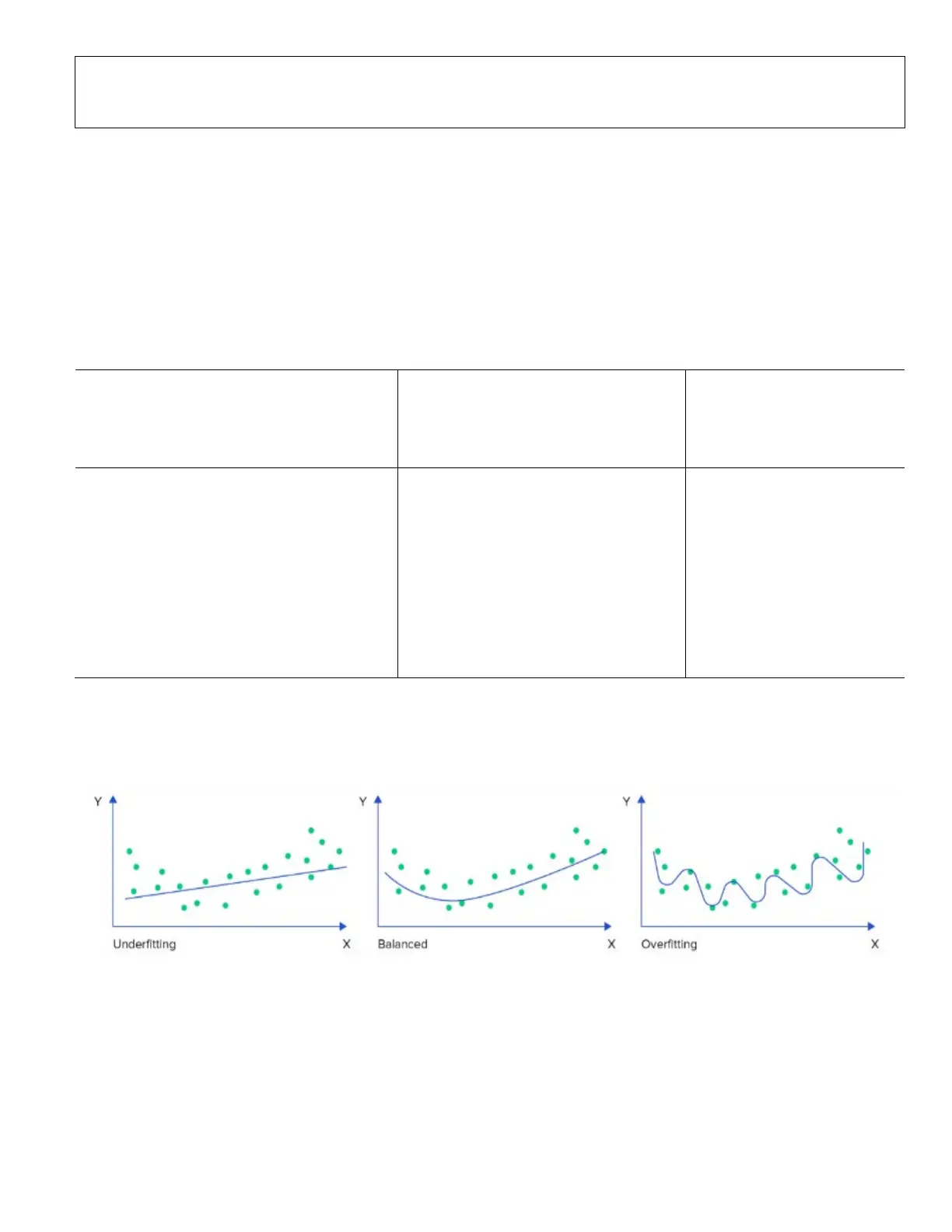
DPD regularization is used to make the DPD coefficient estimation less sensitive to missing data and prevent over-fitting. The
DPD is essentially a curve fitting process, and Figure 25 outlines the optimum fitting to achieve in a system. A higher
regularization prevents over-fitting, in turn improving stability but limiting the ACLR improvement. On the other hand, a low
regularization allows for better ACLR improvement, but stability of the DPD needs to be kept in check.
Figure 25. Comparison of Underfitting, Overfitting and Balanced Fitting
The AM-AM characteristics of a PA for a case where there is sparse data in the high power region is Shown in Figure 26. In this
case, a low regularization value would result in overfitting and causing instability.
 Loading...