Preliminary Technical
Data
Rev. PrA | Page 23 of 82
DPD ROBUSTNESS
This section provides an overview of the features that enhance DPD robustness. These features include DPD stability metrics and
flexible architecture for setting up recovery actions based on these pre-defined DPD metrics. The user can optionally turn on the
DPD robustness feature to protect DPD against erroneous adaptations in abnormal conditions.
In the transceiver DPD, abnormal conditions are detected by monitoring the following metrics:
1. Indirect error that indicates if the pre-distorted samples match the expected result after experiencing PA distortion
2. Transmit capture RMS power
3. Transmit capture peak power
4. Observed capture RMS power
5. Observed capture peak power
6. Post-DPD Capture Tx to ORx EVM (Indirect EVM) which is a measure of non-linearity in the gain line up
7. Pre-DPD capture Tx to ORx EVM (Direct EVM) which is a measure of DPD linearization performance
From a user’s point of view, there are two sets of actions that are required to be taken:
• Define the fault conditions via adi_adrv9025_DpdFaultConditionSet() API
• Provide user-configurable thresholds and actions for fault conditions defined in previous step via
adi_adrv9025_DpdRecoveryActionSet() API
Example: measure transmit capture power, if power < threshold, abandon adaptation
Calculation of Metrics
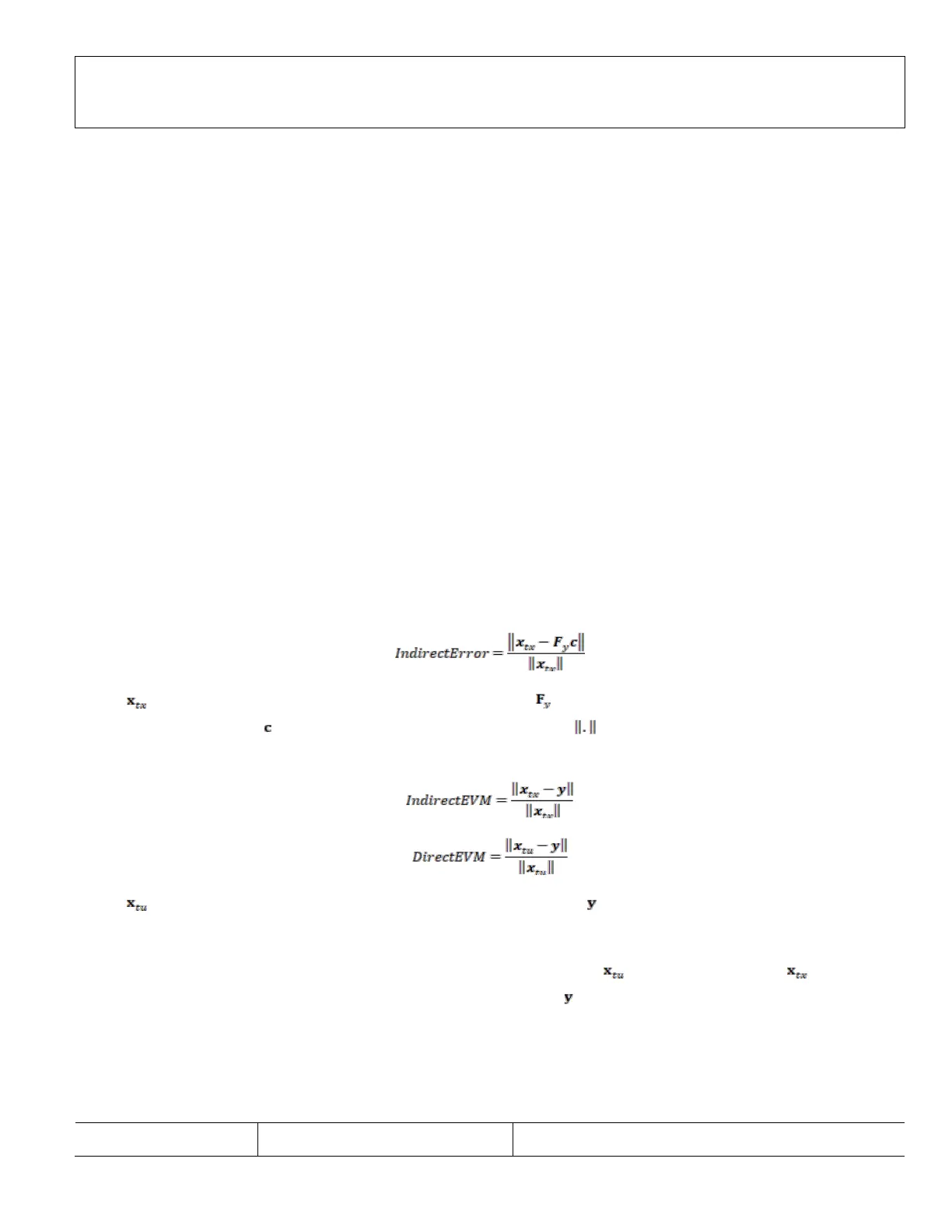
After estimation of the DPD coefficients, the error between the predicted and measured predistortion is computed to determine
the expected DPD performance. Detection of a large error prevents application of bad coefficients can be calculated using the
following equation:
where
is a vector of Tx samples after DPD actuator (post-DPD data); is a matrix of features (such as items in GMP)
formulated by ORx samples;
is the DPD coefficients vector; and the operator is the (Euclidean) norm of vectors.
Similarly, indirect EVM and direct EVM are calculated using the following equations:
where
is a vector of Tx samples before the DPD actuator (pre-DPD data) and is a vector of ORx samples. All samples are
time aligned and gain and phase equalized. The size of the vectors is the number of samples used in each update of the DPD
coefficients.
Transmit signal mean and peak power are calculated from the pre-DPD samples in
and post-DPD samples in , respectively.
Observation receiver mean and peak power are calculated by the samples in
.
Defining Fault Conditions
The user can define fault conditions through the data structure adi_adrv9025_DpdFaultCondition_t described in Table 6. The
fault conditions are programmed through the API adi_adrv9025_DpdFaultConditionSet().
Table 6. DPD fault condition definition data structure adi_adrv9025_DpdFaultCondition_t
Member Data Type Description
 Loading...