Preliminary Technical
Data
Rev. PrA | Page 61 of 82
CLGC ALGORITHM OVERVIEW
The CLGC algorithm is designed to maintain a constant loop gain, and overcome any minor fluctuations in the PA output power
due to variations in temperature and other operating conditions. Loop gain is defined as the ratio of the power level of observed
data to the power level of the baseband transmit data
=
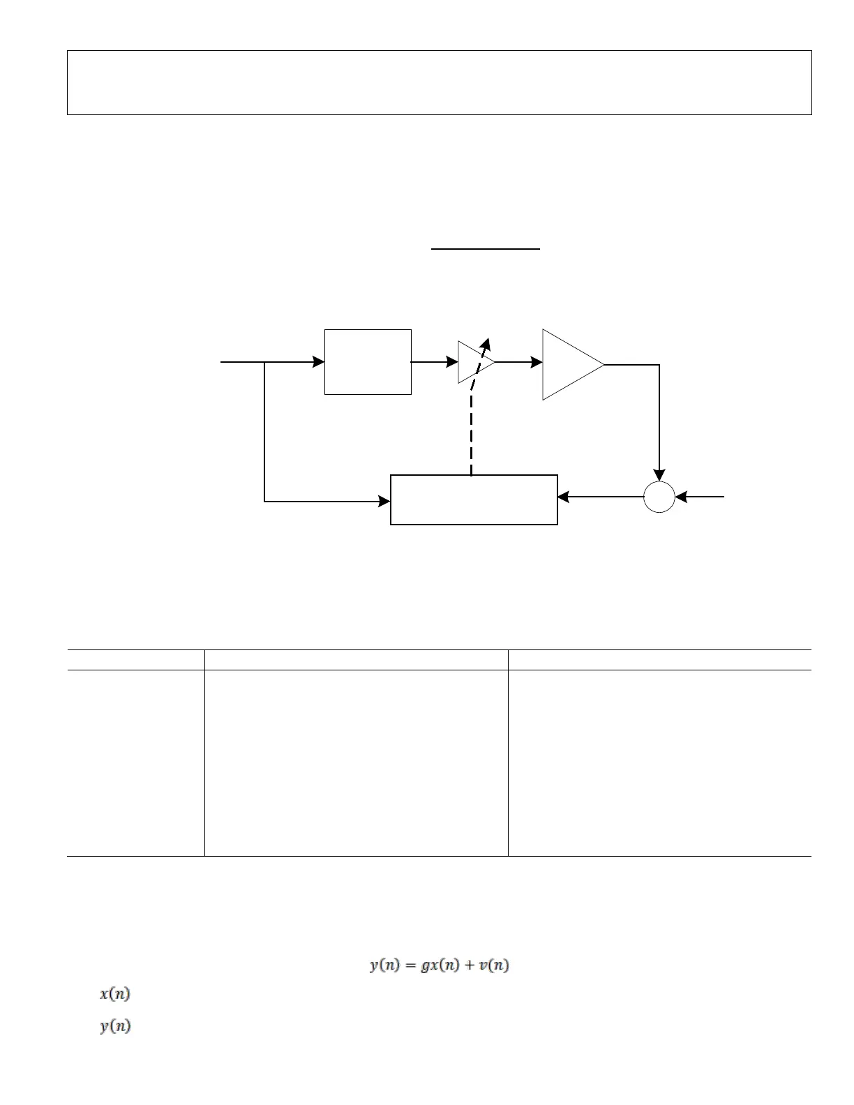
The CLGC algorithm relies on the post PA feedback data to estimate the loop gain and adjust the front end Tx attenuation on the
transceiver. Shown in Figure 3 is the observation points of the CLGC algorithm.
DPD + Tx
Chain
Loop Gain Estimation
and Tx Atten Ctrl
PA
Tx FE Attenuation
+
+
v
x
From DPD Half Band
Interpolators
y
Figure 64. CLGC Algorithm observation points
The signal path from the reference baseband Tx input to the observed data for loop gain estimation can be divided into 4 sections
listed below. The total loop gain observed at the observation receiver(ORx) includes the front end attenuation out of the
transceiver, gain of the power amplifier, coupling attenuation for feedback and the observation receiver(ORx) front end
attenuation.
Table 33. Observed data for loop gain estimation
Xtx(n) = gTX + (x(n) + vtx_DAC_Quant(n))
gTX = Total Tx Attenuation
x(n) = Tx baseband data
vtx_DAC_Quant = Tx DAC quantization noise
XPA(n) = gPA. Xtx(n) + vPA(n)
gPA = PA gain at the PA operating point
vPA = Additive noise determined by ACLR
Yorx(n) = gCPL.XPA(n) + vorx(n)
gCPL = Coupling attenuation in the ORx path
vorx = In band thermal noise and additive noise
determined by noise figure in ORx path
y(n) = gorx. Yorx(n) + vorx_ADC_Quant(n)
gorx = Front end ORx attenuation
vorx_ADC_Quant = ORx ADC quant noise.
Total gain seen at y(n),
g = gorx. gCPL. gPA. gTX
Observation
The ORx samples can be related to the Tx samples in the loop gain estimation engine through the following equation-
•
is the input Tx samples from a user’s BBIC
•
is the output samples from ORx;
 Loading...