Preliminary Technical
Data
Rev. PrA | Page 39 of 82
After loading the waveform, set the ‘Tx attenuation’ to get the desired output power. The waveform is transmitted using the ‘Play’
button on the transmit tab. After playing the waveform, the user can read the power at the output of the PA via a spectrum
analyzer or a power meter (more accurate method).
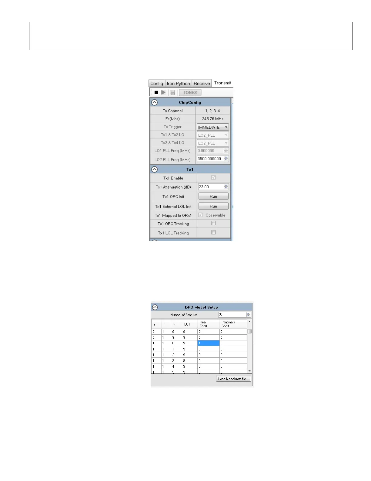
Figure 45. Setting Tx Attenuation and Playing the Waveform
The user can check to make sure ORx is not saturated or too close to the noise floor using the ‘Obs Rx’ tab. ORx gain can be
adjusted to get appropriate signal levels.
On the DFE tab, there is a specific sub-tab for DPD. DPD sub-tab allows the user to fully configure and observe DPD. The ACLR
measurement window is not available at this point (play button is not functional and is not used to enable any DPD feature). The
following steps outline the sequence to configure DPD:
1. Load model file from PC (model files are provided by ADI). Make sure Real Coeff of the linear term (i=1, j=1, k=0) is set to 1.
Figure 46. Load DPD model file
2. Configure ‘DPD Tracking Config’ parameters (default values provide a good starting point).
 Loading...