G
-3- -4-
07
08
09
10
10
+DC12V
Ue=
100%
K3
A1 A2
KM
M
1 L1
3 L2
5 L3
L1
L2
L3
380 V
50/60HZ
2T1
4T2
6T3
(MCCB)
(ELCB)
A2
B2
C2
(KM)
N
或
L1
K2
K1
FU
01
02
03
04
05
06
11
12
G
1
3
5
2
4
6
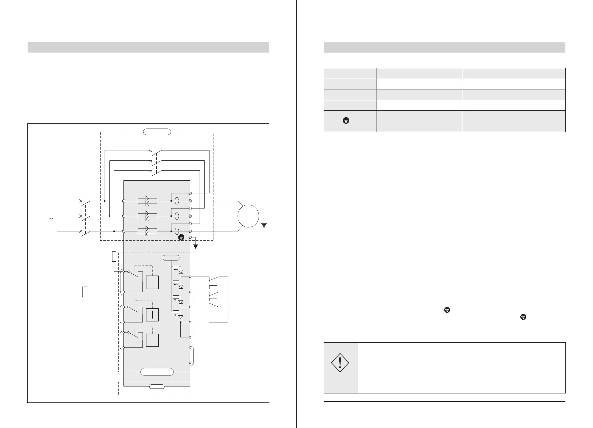
2. Installation and wiring
Please pay attention to the following points when wiring. Refer to diagram 2-3-1
for basic wiring
The power supply must be connected with terminals 1L1, 3L2 and 5L3 of main circuit, no phase
requirement. If there is any wrong connection, it will damage the soft starter.
The ground terminals must be earthed finely, so that it can avoid electric shock or fire accident,
and it can reduce the noise.
The two terminals of lead should be compressed joint to assure high reliability in connection.
2-3 Wiring
Diagram 2-3-1
Diagram of
basic wiring
Power
supply
3-phase
Equipped with
circuit breaker
Or
Leakage
circuit breaker
Full voltage
output
Time delay
output
(Programmable)
Fault output
Main circuit
Equipped with bypass electromagnetic contactor
Instantaneous stop
Stop
Start
Common port
Analog output
(DC 0-20mA)
Control circuit
RS485 communication
2. Installation and wiring
2-4 Wiring of main circuit and earth terminal
Table 2-4-1 Function of main circuit and earth terminal
(1) Power supply input terminals of the main circuit (1L1, 3L2, 5L3)
Power supply terminals 1L1, 3L2 and 5L3 of main circuit connect with 3-phase power supply
through protective circuit breaker or leakage circuit breaker. It is not necessary to consider the
connecting phase sequence.
Please do not adopt the ON/OFF control method (power supply of main circuit) to start or stop
the soft starter, you should electrify the soft starter first, and then make use of the control terminal
that on the soft starter or the RUN and STOP keys to run or stop the machine.
Please do not connect with single-phase power supply.
(2) Output terminals of soft starter (2T1, 4T2, 6T3)
Connect the output terminals of the soft starter with 3-phase motor in correct phase sequence.
If the rotation direction of the motor is wrong, you can exchange the connection of any two pha-
ses of 2T1, 4T2 and 6T3.
The output side of the soft starter can not be connected with capacitor and surge absorber.
When the wire between soft starter and motor is very long, the distributed capacitance among
the wire will produce high frequency current, it may cause phenomenon like over current and
trip, more leakage current, low accuracy of current display, etc. Therefore, we suggest that the
wire for motor connection should be less than 50m.
(3) Bypass connection (A2, B2, C2)
The bypass connection terminals A2, B2 and C2 must be connect with the electromagnetic by-
pass contactor, otherwise, the soft starter would be burned. After the soft starter is started, the
power device of major loop (silicon controlled rectifier) exits, meanwhile, the bypass electrom-
agnetic contactor works, and the motor runs normally, pay attention to the phases, they cannot be
wrong connected.
(4) Grounding terminal of soft starter ( G)
In order to reduce noise and for safety consideration, the grounding terminal G of the soft
starter must be firmly earthed. In order to avoid electric shock and fire accident, the metal enclo-
sure and frame of the electric equipment should comply with the national electric requirements.
Terminal mark
1L1, 3L2, 5L3
2T1, 4T2, 6T3
A2, B2, C2
Terminal name
Power supply input of main circuit
Output connection of soft starter
Bypass connection
Grounding terminal of soft
starter
Description
Connect with 3-phase power supply
Connect with 3-phase motor
Connect with bypass electromagnetic contactor
The grounding terminal of the case
of soft starter should be earthed firmly
Confirm that the input phase number and rated input voltage of the soft starter should be accord
with the phase number and voltage value of the AC power supply.
The AC power supply can not connect with the output terminals (2T1, 4T2, 6T3, A2, B2, C2)
The bypass electromagnetic contactor must be connected, and the phase sequence can be wrong
connected.
Otherwise, there may be accidents happen.
Danger
 Loading...