01
02
A1 A2
KM
L1
N or L3
FU
380V
50/60HZ
ON
OFF
M
1 L1 3 L2 5 L3
2 T1 4 T2 6 T3
A2
B2
C2
(KM)
L1 L2 L3
(AJR3-1000)
1 3 5
2 4 6
-5- -6-
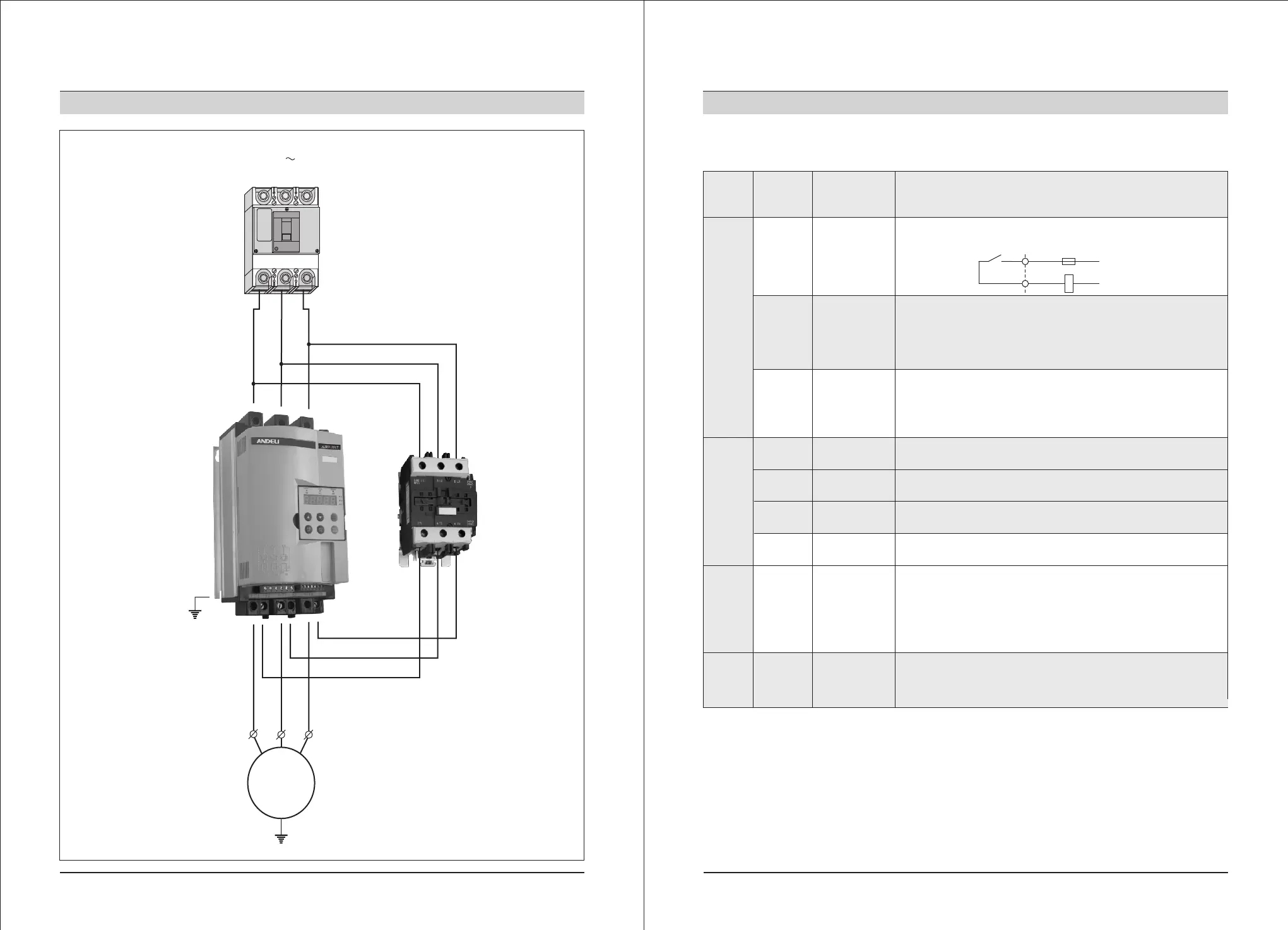
2. Installation and wiring
2-5 Wiring diagram of main circuit of the ANDELI AJR3-1000 soft starter
3-phase power supply
(MCCB)
(ELCB)
Equipped with
circuit breaker
Or
Leakage
circuit breaker
Motor soft
starter
Equipped with
bypass electr-
omagnetic co-
ntactor
3-phase asynchronous motor
2. Installation and wiring
Please refer to the table 2-6-1 for the function of control terminals. According to different
function setting, the function and connection of the control terminals will be different.
Table 2-6-1
2-6 Wiring of control terminals
Classi-
fication
Terminal
mark
Terminal
name
Function description
Contact output
01, 02
Bypass
output
When the soft start is finished starting, 01 and 02 closed
and control the bypass electromagnetic contactor.
03, 04
Operation
output
(Time delay)
03 and 04 are programmable relay output, the delay
time is set by code P4. Output function time is set by
code PJ, as NO, close when the output is effective.
(Contact rating AC 250V/3A).
05, 06
Fault
output
05 and 06 are programmable fault relay output, they
will close when there is fault or it is power cut, and
they will open when it is power on.
(Contact rating AC 250V/3A).
Contact input
07
Instantaneous
stop input
When 07 and 10 are open, the motor will stop working imm-
ediately (or joining up in series with NC of other protectors).
(1) Contact input terminal
When use external terminals to control soft starter to start or stop, please set the PD into exte-
rnal control is effective.
If need remote control, we suggest using (two wires) control mode, please refer to 2-8 in Page 8
(two wires control mode).
Usually, the contact signal input terminal and common terminal will do close/open (ON/OFF)
actions, the soft starter, motor and conductor arrangement will produce interference, therefore,
please use shorter wire (shorter than 20m), and use shielding conductor for cable.
The conductor arrangement of control terminal should be far away from the wiring of main
circuit. Otherwise, there may be error operation caused by interference.
08
Soft
stop input
When 08 and 10 open, the motor will speed down and
soft stop. (Or free stop)
09
Starting
input
When 09 and 10 close, the motor will start to run.
10
Common
terminal
The common terminal for contact to input signal.
Analog output
11, 12
Analog
output
11 and 12 is analog output for DC 4~20mA, it is used
to monitor the running current of motor, when it is full
range 20mA, it is 4 times of nominal rated current, it
can be connected with 4~20mA ammeter for monitoring
signal outside, its max resistance of output load is 300Ω.
Commu-
nication
DB
RS485 communication
Input/output
The input/output signal terminal of RS485 commu-
nication, can be used to connect several soft starters.
 Loading...