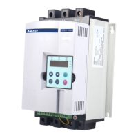
AJR3-1000-5.5KW~75KW
1/L1 3/L2 5/L3
2 /T1 4/T2 6/T3
A2 B2 C2
G
AJR3-1000-90KW~500KW
1/L1 3/L2 5/L3
2 /T1 4/T2 6/T3
A2 B2 C2
1/L1 3/L2 5/L3
2 /T1 4/T2 6/T3
G
01 02 03 04 05 06
07 08 09 10 10 11 12
AJR3- 1000AJR3- 1000
07
08
09
10
10
07
08
09
10
10
K
Wire for control terminal0.75~1.25mm
2
07
08
09
10
10
KA
K
KA
KA
L N
07
08
09
10
10
KA
K
KS
KA
L N
07
08
09
10 10
A1
A2
KM
M
1 L1
3 L2 5 L3
2 T1 4 T2 6 T3
(QF)
A2
B2
C2
(KM)
N or L1
FU
(DC0-20mA)
01
02
03
04
05
06
11
12
G
L1 L2 L3
A
- +
1 3 5
2 4 6
1 3 5
2 4 6
-7- -8-
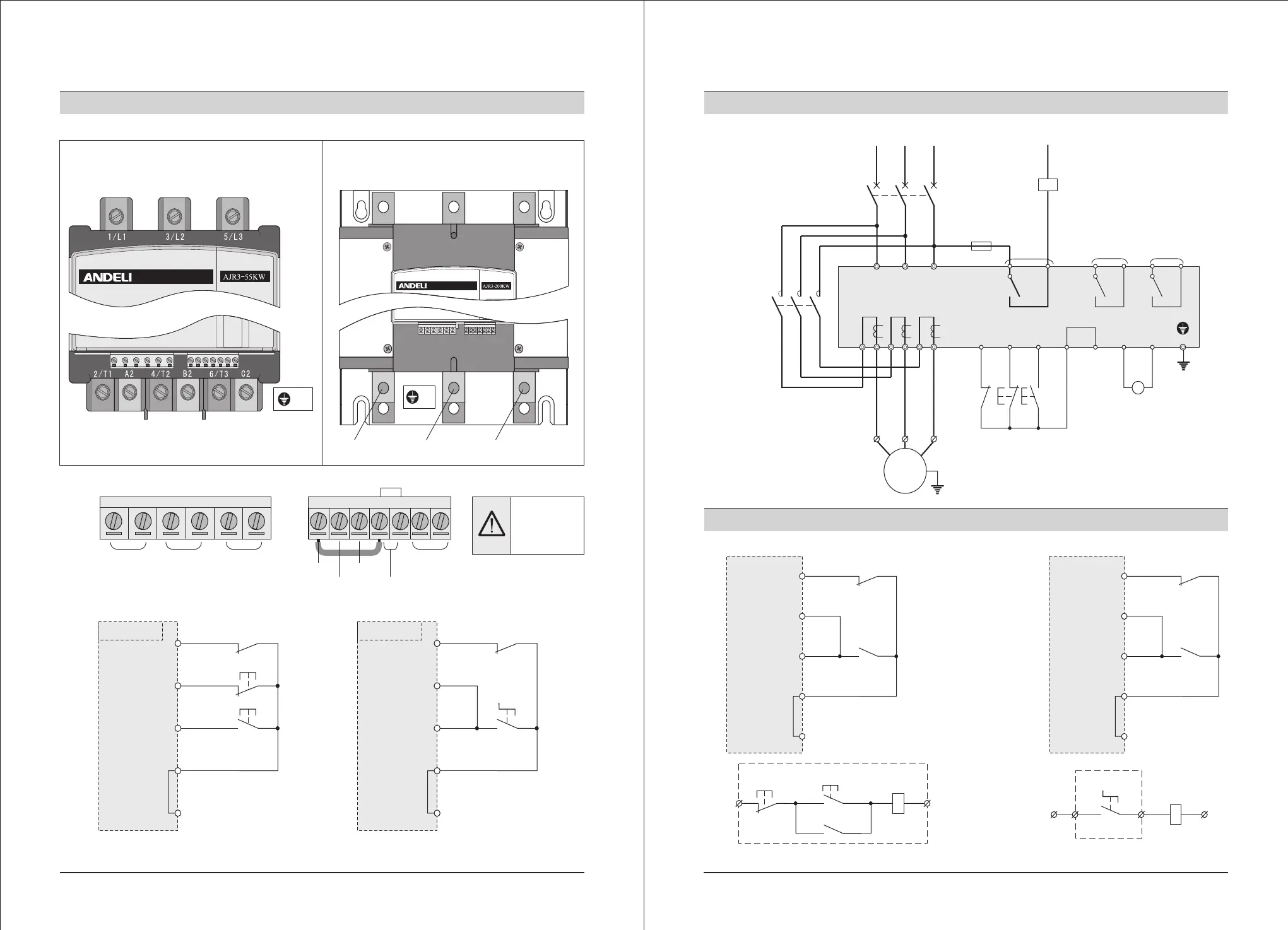
2. Installation and wiring 2. Installation and wiring
2-7 Layout diagram of control terminals
(1) Terminals of main circuit
(2)Terminals of control circuit
Bypass
output
Running
output
Fault
output
Instantaneous
stop
Soft
stop
Start
Common
terminal
Analog
output
It is forbidden
to input power
supply to 07-12
terminals
(3) Terminals wiring of control circuit
Three-wires control mode Two-wire control mode
Instantaneous stop
Stop
Start
Common terminal
Instantaneous stop
Stop
Start
Common terminal
When K closes, it will start running,
when it open, it will stop running
2-8 Diagram of primary and secondary wiring of ANDELI AJR3-1000
Bypass electromagnetic contactor
Circuit
breaker
Full
voltage
output
Time
delay
output
Fault
output
Instantaneous
stop
Stop
Start
Common
terminal
Analog output
2-9 Wiring diagram of relay and remote control
Control mode of relay
Remote control mode
Instantaneous stop
Stop
Start
Common terminal
Instantaneous stop
Stop
Start
Common terminal
K is the NC point for other protectors (such as thermal protector), it is short-connection when leave the factory.
 Loading...