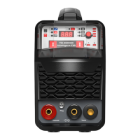
This document is the owner's manual for the MCT-520DPL PRO, a multifunction welding and cutting machine.
Function Description
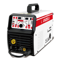
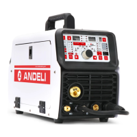
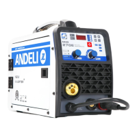
The MCT-520DPL PRO is a versatile, multi-purpose machine designed for various metalworking tasks. It integrates four primary functions: MIG (Gas Metal Arc Welding), TIG (Gas Tungsten Arc Welding), CUT (Plasma Cutting), and MMA (Manual Metal Arc Welding, also known as Stick Welding). This makes it suitable for a wide range of applications, from cutting stainless steel, alloy steel, carbon steel, and other non-ferrous metals, to welding stainless steel and carbon steel products. The machine is particularly highlighted for its use in welding scooters, bicycles, and similar products.
The core of the MCT-520DPL PRO's operation lies in its high-frequency inverter technology. This technology first rectifies the 50/60Hz AC input to DC, then converts it into a high-frequency voltage using an Insulated Gate Bipolar Transistor (IGBT) through Pulse Width Modulation (PWM). This high-frequency voltage is then reduced and rectified to output high-power DC, significantly reducing the machine's volume and weight while increasing efficiency by over 35%.
Key features stemming from this inverter technology include:
- High Efficiency and Energy Saving: The inverter design contributes to substantial energy savings.
- Light Weight and Small Size: Compared to traditional machines, it is more portable and compact.
- No Electromagnetic Noise: Operates with minimal electromagnetic interference.
- Good Dynamic Characteristics: Ensures stable performance during operation.
- Stable Arc and Easy Control of Molten Pool: Provides consistent and controllable welding.
- High No-Load Voltage and Good Ability Compensation: Enhances its adaptability to various power grid conditions.
- Pure Square Wave Output (for TIG): This feature ensures good arc stiffness, concentrated heat, excellent reverse cleaning ability, and a wide cleaning range. It also makes the arc less prone to breaking at small currents, contributing to superior welding characteristics.
The machine also includes a foot pedal current regulating device, allowing the welder to adjust the current hands-free. This facilitates quick heating at the start of welding, efficient wire addition, and current reduction at the end of the weld, improving welding efficiency, reducing difficulty, and ensuring quality.
Important Technical Specifications
The MCT-520DPL PRO operates on an AC220±15% input voltage with a frequency of 50/60 Hz. Its technical parameters vary by mode:
| Parameter |
CUT |
TIG |
MMA |
MIG |
| Rate input current (A) |
40 |
26 |
40 |
34 |
| Current Range (A) |
20-50 |
10-200 |
10-200 |
50-200 |
| No-load voltage (V) |
310 |
64 |
64 |
64 |
| Rate output voltage(V) |
100 |
18 |
28 |
24 |
| Ignition way |
HF |
HF |
TOUCH |
TOUCH |
| Efficiency (%) |
77 |
77 |
77 |
77 |
| Duty Cycle (%) |
30 |
30 |
30 |
30 |
| Power factor |
0.73 |
0.73 |
0.73 |
0.73 |
| Insulation Class |
H |
H |
H |
H |
| Housing Protection Class |
IP21S |
IP21S |
IP21S |
IP21S |
The machine weighs 14.3 kg and has dimensions of 490x215x325 mm. It is equipped with a power voltage compensation device, allowing it to operate normally even if the power voltage fluctuates within ±15% of the rated voltage.
Usage Features
The MCT-520DPL PRO offers a user-friendly control panel with digital displays for various parameters, including job number, current, wire feeding speed, Hertz, voltage, pulse width, and pulse time.
Control Panel Features:
- Wire Check Button: For checking wire feed.
- Welding Model Selection: Allows selection between MIG 2T/4T, Plasma CUT, HF TIG, SPOT, and MMA modes.
- MIG Synergic/Manual/TIG PULSE Selection: For choosing MIG Synergic (wire diameter), MIG Manual, or DC Pulse TIG modes.
- TIG Parameter Selection Buttons: To navigate and select different TIG parameters (move right/left).
- Parameter Adjust Knob: For increasing or decreasing various parameters.
- Function Selection Buttons:
- In MIG mode: Selects CO2 / mixed gas / gasless, or VRD (Voltage Reduction Device) in MMA mode, or 2T/4T trigger in TIG mode.
- In MMA mode: Selects Hot-start / Hot-start time / Arc-force.
- In MIG mode: Selects Inductance.
- In CUT mode: Selects 2T/4T trigger.
- Job Storage Button: Allows calling saved jobs (10 groups available). Parameters are saved automatically after 5 seconds without adjustment.
- Gas Check Button: For checking gas flow.
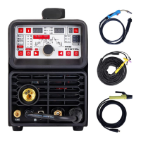
Installation and Operation Highlights:
- Wire Reel Installation: Detailed steps are provided for installing the wire spool, adjusting tension, and threading the welding wire. It emphasizes selecting the correct wire feeding groove based on wire dimension (U-shape for aluminum, V-shape for others) and avoiding excessive tension to prevent wear.
- MIG Welding Installation: Involves connecting the MIG Torch Euro Connector, ensuring correct gas-shielded wire, drive roller, and welding tip are fitted, connecting the polar conversion line to the positive terminal, earth lead to the negative terminal and workpiece, and connecting the gas cylinder to the MIG gas inlet. The manual specifies changing to a graphite guide wire tube and U-shaped roller for aluminum welding.
- TIG Welding Installation: Requires connecting the Lift TIG torch to the negative terminal, earth lead to the positive terminal, and the air hose to the Argon meter connector. Gas cylinder connection is also detailed.
- Cutting Installation: Involves connecting the cutting torch, polar conversion line to the negative terminal, earth lead to the positive terminal, and the air compressor to the CUT gas inlet.
- MMA Welding Installation: Connects the electrode holder to the positive terminal and the earth lead to the negative terminal and workpiece.
- VRD Function: In MMA mode, the VRD (Voltage Reduction Device) can be turned on or off. When on, the no-load voltage drops to 15V for enhanced safety.
- Hot Start and Arc Force: Adjustable parameters in MMA mode to facilitate easier arc starting and better welding results.
- Cold Welding: A specific function suitable for thin plate welding in TIG mode.
- Adjustments: Welding voltage, wire feeding speed, and cutting current can be adjusted via the knob. The manual explains the effect of these adjustments on arc length, melting depth, melting width, and cutting thickness.
Maintenance Features
The manual provides crucial information regarding maintenance and troubleshooting to ensure the longevity and safe operation of the machine.
Safety Warnings:
- Electric Shock: Emphasizes connecting the earth cable, avoiding contact with live electrical parts, wearing dry welding gloves, and insulating the workpiece.
- Smoke and Gas: Warns against breathing welding fumes and stresses the need for good ventilation.
- Fire Hazard: Advises removing flammable materials from the work area and having a fire extinguisher readily available.
- Noise: Recommends wearing approved ear protection.
- Electric Leakage Protection: A critical warning to add an electric leakage protecting switch when using the machine.
- Prohibition of Cable Removal During Operation: Strictly forbids inserting or removing cables or connectors while the machine is in use, as this can endanger personal safety and damage the equipment.
General Precautions:
- Environment: Welding should be performed in a relatively dry environment (humidity < 90%), between -10°C and 40°C. Avoid welding in daylight or rain, dusty areas, corrosive atmospheres, or strong airflow.
- Ventilation: Good ventilation is crucial. The fan must not be covered or blocked, and a minimum distance of 0.3 meters from surrounding objects should be maintained.
- No Current Overload: Users must adhere to the maximum allowable load current and duty cycle to prevent damage and shorten the lifespan of the welder.
- Voltage Control: While the machine has voltage compensation, exceeding the allowable input voltage range can still cause damage.
- Grounding: A grounding screw is provided, and reliable grounding with a cable larger than 6mm² is mandatory to prevent static electricity or electric leakage accidents.
- Overheat Protection: The machine has overvoltage, overcurrent, and overheat protection circuits. If it enters a protection state (digital display shows -E2), the cooling fan will continue to operate until the temperature drops to a safe range, allowing for restart.
- Warranty: The warranty is void if users attempt unauthorized checks or repairs for malfunctions.
Troubleshooting and Fault Finding:
The manual includes a comprehensive troubleshooting guide with fault symptoms and corresponding remedies.
- Regular Cleaning: Dust should be removed regularly with dry, compressed air, especially in polluted environments. Compressed air pressure must be reasonable to avoid damaging internal components.
- Circuit Checks: Regular inspection of internal circuits, cable connections, and connectors for tightness and cleanliness is recommended. Any scale or looseness should be polished and reconnected tightly.
- Moisture Prevention: Avoid water and steam ingress. If moisture enters, the machine must be dried, and insulation checked.
- Storage: For long-term storage, the machine should be packed in its box and kept in a dry environment.
Specific Fault Symptoms and Remedies:
- No Power/Fan/Welding Output: Check power switch, input cable, and grid connection.
- Power On, Fan/Welding Output Issues: Could be due to incorrect voltage input (e.g., 380V instead of 220V), unstable input voltage, rapid power cycling, loose wires, or damaged relay.
- Fan On, No High-Frequency Discharge/Arc Start: Check voltage at MOS board, auxiliary power supply indicator, patch cord connections, control circuit, or welding torch control line.
- No Welding Output with High-Frequency Discharge: Check welding gun cable, ground wire, or positive/torch gas output terminal connections.
- Arc Welding Starts, No High-Frequency Discharge: Check arcing transformer primary line, discharge nozzle condition/distance, or high-frequency arc-trigger circuit components.
- Abnormal Indicator On, No Output: Indicates overcurrent or overheat protection, inverter circuit fault, or issues with the high-frequency pilot arc power supply or main transformer. Detailed steps are provided to diagnose and replace damaged components like FETs or transformers.
- Inability to Break Oxide Film (Aluminum Welding): Suggests incorrect welding gear selection, too small a duty cycle adjustment, or secondary inverter field tube damage.
- Tungsten Needle Burnt Seriously: Indicates the duty cycle is adjusted too high.
The manual also includes an "EXPLOSIVE VIEW" diagram with a list of components, indicating which parts are "consumables" (e.g., double pressure plate, main board, fan, PCB control panel, high frequency board, control board, rectifier bridge, IGBT, fast recovery diode, rectifier board). This aids in identifying and replacing parts during maintenance.