Do you have a question about the ANDELI MIG-270E and is the answer not in the manual?
Provides essential safety rules and precautions to follow during operation.
Instructions to prevent electrical hazards like shock and burns during welding operations.
Safety measures against harmful fumes, gases, and ensuring proper ventilation.
Guidelines on protecting eyes and skin from welding arc, sparks, and hot slag.
Precautions to prevent fires, explosions, and mechanical accidents in the welding environment.
Warnings against moving parts, safe gas cylinder handling, and machine movement precautions.
Explains that welding causes electromagnetic interference and how to minimize it.
Guidance on evaluating the surrounding environment for potential electromagnetic disturbances before installation.
Discusses methods to reduce electromagnetic radiation from the welding equipment.
Details on power supply connection, cable setup, and earthing for EMC.
A detailed table listing specifications like voltage, current, duty cycle, and dimensions.
Specifies the ideal environmental conditions for installing and operating the welding machine.
Details the necessary specifications for the input power source to ensure proper operation.
Lists input power requirements and protection details, including cable specifications.
Step-by-step guide for connecting the welding machine to the power supply for MMA and MIG.
Overview of the primary functions and controls available on the welding machine.
Describes the layout and purpose of the control panel and its interface elements.
Details how to select functions and set parameters for the MIG-120 model using controls.
Explains the function of control knobs and specific modes like Lift TIG, MMA, and Flux cored wire.
Explains the function of power and overload indicator lights on the machine.
Explains the AUTO function and its synergic indicator light for automatic parameter adjustment.
How to adjust welding voltage and set current based on plate thickness.
Details the various output sockets (MIG torch, cathode) and their connections on the welding machine.
Describes anode output sockets, polarity conversion for MIG torch, and connections for different modes.
A table listing welding materials, their abbreviations, and corresponding gases.
Specific instructions for setting up and performing MMA welding, including DC EP configuration.
Configuration for DC Electrode Negative (EN) in MMA welding.
A reference table for recommended welding current and voltage based on electrode diameter.
Instructions for setting up and performing gas shield (MIG) welding.
Guidelines for using flux-cored wire without external gas.
Instructions for performing Lift TIG welding, including arc starting.
Reference parameters for TIG welding of titanium and alloy materials.
Critical safety considerations, including protection circuits and operating limits.
Emphasizes good ventilation and warns against overloading the welding machine.
Caution against high voltage and prohibits using the machine for non-welding tasks.
General maintenance instructions, including cleaning and checking connections, with a critical power warning.
Procedures for regular dust removal and checking internal connections for optimal performance.
Steps to prevent moisture ingress and essential warnings before starting any maintenance.
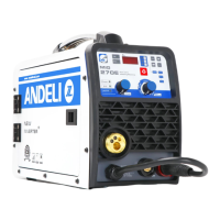
The ANDELI MIG-270E is an inverter MIG welding machine that combines two functions in one: MMA and MIG welding. This versatile machine is suitable for welding various materials, including carbon steel, stainless steel, copper, and titanium. It offers excellent static load and dynamic characteristics, along with a comprehensive set of control functions.
The MIG-270E utilizes IGBT high-frequency soft switch technology, which contributes to its high efficiency, compact size, and portability. Its advanced control system significantly enhances welding performance, allowing it to meet a wide range of welding process requirements. The machine supports both MIG and MMA welding modes, making it a 2-in-1 solution for various applications. Key features include easy arc starting, a stable arc, and high performance. It also produces minimal spatter, maintains a stable current, offers high reliability, and ensures good weld-seam shaping.
The welding machine operates by taking a 220V power input, rectifying it, and then sending it to an inverter composed of IGBTs and other components to generate high-frequency alternating current. This high-frequency AC is then stepped down by a high-frequency transformer, rectified, and filtered to produce the DC current suitable for welding. This process improves the welder's dynamic response, reduces the volume and weight of the transformer and reactor, and enhances the overall efficiency of the machine. The control circuit is designed to ensure consistent welding performance even when external conditions change, such as grid voltage fluctuations or varying output cable lengths. This results in easy arc starting, a stable arc, well-formed welds, and continuously adjustable welding current.
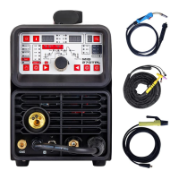
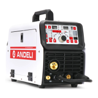
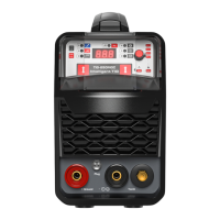
The front panel of the MIG-270E serves as the primary interface for selecting functions and setting welding parameters. It includes a knob for function selection, allowing users to switch between Lift TIG, MMA, and Gasless flux-cored wire (0.8/1.0mm). The "Lift TIG" function enables arc starting by contacting the workpiece and then lifting the torch, without requiring high frequency. The "MMA" mode is for manual metal arc welding. For flux-cored wire welding, users can select between 0.8mm and 1.0mm wire sizes.
Indicator lights provide important feedback: a "POWER" light signals that the machine is on, and an "O.C" (Over Current/Over Temperature) light indicates an over-temperature or abnormal condition. If the machine overheats, it enters a protected state and stops working; after cooling, it can resume normal operation. An over-current indication might suggest a component issue, prompting a restart after inspection. The "AUTO" indicator signifies the synergic mode, where current and voltage automatically adjust and match, particularly under Gasless MIG mode.
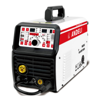
The front panel also features a "Voltage" knob for fine-tuning the welding voltage in Gasless MIG mode, allowing for both decreasing (negative value) and increasing (positive value) adjustments. A "Plate Thickness" knob is used to set the current value in Lift TIG, MMA, and Gasless MIG modes.
The welding output interface includes a MIG torch socket, a cathode output fast socket (for connecting a TIG torch in Lift TIG mode or the workpiece in MMA mode), and an anode output fast socket (for connecting the workpiece in Lift TIG mode or the electrode holder in MMA/Gasless MIG mode). For MIG-120 and MIG-160 models, specific polarity conversion joints are available for the MIG torch, allowing connection to the anode in MIG mode and Gasless MIG mode. The cathode output fast socket connects the TIG torch in Lift TIG mode or the workpiece in MMA/MIG mode. The anode output fast socket connects the workpiece in Lift TIG mode or the electrode holder in MMA/Gasless MIG mode.
Installation: The MIG-270E should be installed in a dry environment with humidity below 90% at 20°C and 50% at 40°C. The operating temperature range is -10°C to 40°C, and for storage and transportation, it is -20°C to 55°C. The machine should be protected from direct sunlight and rain. It is advised to avoid using it in environments with strong airflow, especially during TIG welding, and in dusty, acidic, or corrosive conditions. The welding power source's inclination should be less than 10°, and the altitude should not exceed 1000m. To ensure proper ventilation and operation, the machine should be placed at least 20cm from walls and 10cm from other welding machines.
The input power source requires a standard pure sine wave with a fluctuation range of 220V±15% and a frequency of 50Hz/60Hz. The power supply should be single-phase AC 220V/50Hz, connected to a distribution cabinet with an automatic air switch, ensuring safe grounding.
MMA Welding: For MMA welding, connect the welding cable to the machine. Ensure the machine is turned off before connecting the input cable to the distribution cabinet, then switch it on. For DC EP (Electrode Positive), connect the cathode to the workpiece ("-") and the welding torch to the anode ("+"). For DC EN (Electrode Negative), connect the anode to the workpiece ("+") and the cathode to the TIG torch ("-"). The operator should choose the connection method based on the base metal and electrode material; alkaline electrodes are generally recommended for DC reverse connection.
MIG Welding: For MIG welding, connect the earth cable to the negative pole and the feeder cable to the positive pole. Connect the hose to the machine and the gas bottle. Turn off the machine before connecting the input cable to the distribution cabinet, then switch it on.
Gas Shield Welding: Connect the gas cylinder to the CO2 gas regulator, then to the wire feeder pipe, and secure it with a buckle. When using CO2 gas, the regulator should be connected to a heating power source to prevent freezing, which can affect welding quality. This heating power is not needed for mixed gas. Place the welding wire in the correct wire groove according to its diameter. Release the nut on the wire pressing wheel, feed the wire through the wire hose, and adjust the pressing wheel to ensure the wire does not slip. Avoid over-pressing to prevent wire distortion. Connect the wire feeder polarity plug to the positive socket and the earth clamp to the negative fast socket, tightening it clockwise. For the MIG torch, feed the wire out via inspection and select the appropriate contact tip, then tighten and press the gun switch to start. Fine-tuning the voltage is recommended if the current and voltage are mismatched.
Flux-Cored Wire Welding (without gas): Similar to gas shield welding, place the wire in the correct groove, feed it through the hose, and adjust the pressing wheel. Connect the wire feeder polarity plug to the negative socket and the earth clamp to the positive fast socket, tightening it clockwise. For the MIG torch, feed the wire out via inspection and select the appropriate contact tip, then tighten and press the gun switch to start. Fine-tuning the voltage is recommended if the current and voltage are mismatched.
Lift TIG Welding: Connect the gas pipe of the TIG torch to the gas cylinder. Connect the separated-type TIG torch to the negative socket and the earth clamp to the positive socket. To start the arc, scratch the tungsten on the workpiece and then lift the TIG torch. Since there is no control switch for gas flow and current, users should turn off the gas cylinder and keep the torch away from the workpiece to prevent waste and ensure safety.
Safety Points: The welding machine is equipped with overcurrent and overheat protection circuits. It will automatically stop working if the grid voltage, output current, or internal temperature exceeds set standards. However, excessive use, such as operating with excessive voltage, can still damage the machine.
Ventilation: Good ventilation is crucial. During operation, the machine generates significant heat due to large working currents. The built-in fan cools the welder effectively. Users must ensure that the ventilation area is not covered or blocked and that there is at least 0.3 meters of clearance from surrounding objects. Maintaining good ventilation is essential for optimal performance and extended service life.
Overload Prevention: Users must adhere to the allowable load duration specified in the welder's nameplate parameters to prevent current overload, which can significantly shorten the welder's life or even burn it out. The load continuation rate indicates the welding time under load within a 10-minute cycle (working time + rest time = 10 minutes). For example, at 30% duty cycle and 200A/28V, the machine can work for 3 minutes and then requires a 7-minute rest. At 60% duty cycle and 141A/25.6V, it can work for 5 minutes and then needs a 4-minute rest.
Voltage Considerations: Operating the machine with a voltage higher than the specified range (listed in the "main performance parameters" table) can damage the welder, even with the automatic voltage compensation circuit. Users should understand this risk and take preventive measures. The welding machine should not be used for thawing pipes.
Grounding: Each welding machine has a ground screw on the rear panel, marked with a ground symbol. Before use, connect a cable with a cross-section greater than 2.5mm² to reliably ground the welding machine shell. This helps release static electricity and prevents accidents due to electrical leakage.
Protection State: If the welding machine exceeds its standard load duration or if the temperature becomes too high, it will enter a protection state and stop working. The temperature control switch will be triggered, and the yellow indicator light on the front panel will illuminate. In this situation, do not unplug the power supply; allow the cooling fan to continue operating to cool the welder. Once the yellow indicator light turns off, the temperature has dropped to the standard range, and welding can resume.
General Maintenance: All maintenance, service, and cleaning work must be performed with the power removed. Always unplug the power cord before opening the casing. Regular dedusting is recommended using dry, clean compressed air. In smoky or severely polluted environments, dedusting should be done daily. The compressed air should be delivered at an appropriate pressure to avoid damaging internal components.
Connection Checks: Periodically check the internal contact areas, especially plug-in joints or components, to ensure tight connections. If any rusting or oxidation occurs, use sandpaper to remove the oxide film and reconnect.
Moisture Prevention: Prevent water and moisture penetration. If this occurs, dry the inside of the welder thoroughly. Afterward, perform a megger insulation test, including insulation between connection joints, as well as between joints and the casing. Welding should only resume if no errors are detected.
Storage: If the welder will not be used for an extended period, seal it in its original packaging and store it in a dry condition.
Important Warning: Blind experiments or imprudent overhauls can exacerbate failures and make formal maintenance difficult. Electronic equipment with exposed live parts can be dangerous; any direct or indirect contact can lead to electric shocks, which can be fatal. During the warranty period, unauthorized maintenance or repairs to any fault of the welding power source will void the supplier's free repair services.
| Input Voltage | 220V |
|---|---|
| Frequency | 50/60Hz |
| Output Current Range | 30-270A |
| Rated Output Voltage | 28V |
| Duty Cycle | 60% |
| Wire Diameter | 0.8-1.0mm |
| Power Factor | 0.73 |
| Insulation Class | F |
| Protection Class | IP21S |
| Efficiency | 85% |
| Welding Type | MIG |
| Duty Cycle at | 270A |