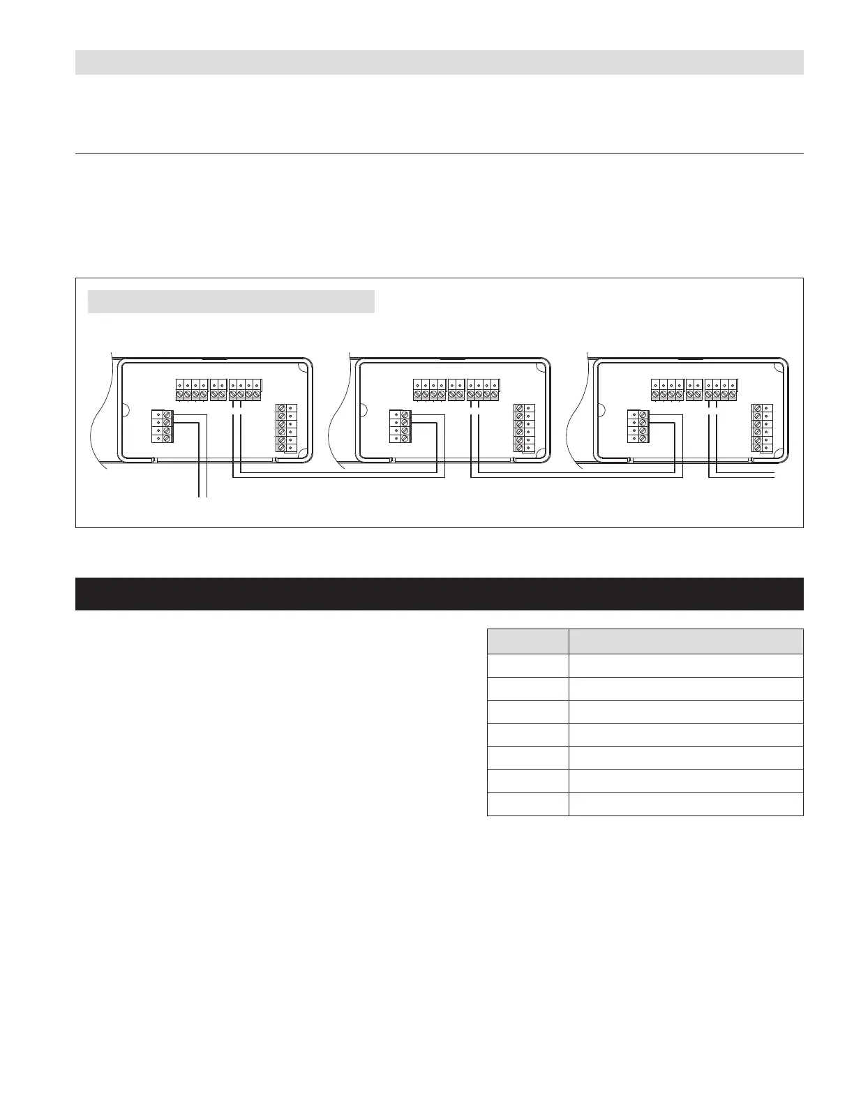
ALTERNATE EXTERNAL DRY CONTACT CONTROL AS DRIVING CONTROL
When a dry contact control is used to control the first dehumidifier, Unit #1 must be set to ENABLE EXTERNAL in the set-up menu� All downstream
units must be set up to ENABLE EXTERNAL in each set-up menu� See page 9 for set up details and wire as shown in FIGURE 13�
SEQUENCE OF OPERATION
Each unit in the daisy chain responds to the first unit being controlled by the external control� When the humidity level rises above the humidity
setting, all units will dehumidify until the humidity measured by the external control falls below the setting�
IMPORTANT: If the external control experiences a fault, all downstream dehumidifiers will also stop function� If any dehumidifier experiences a fault,
that unit will stop operation as determined by the fault but all other units will continue operating� If any unit loses power, all downstream units will
stop function�
+ - A B ODT
SensorRemote
Gh Rf Cf Gs YW
HVAC EQUIP.
Float
Switch
DHDH
Vent
+ - A B ODT
SensorRemote
Gh Rf Cf Gs YW
HVAC EQUIP.
Float
Switch
DHDH
Vent
+ - A B ODT
SensorRemote
Gh Rf Cf Gs YW
HVAC EQUIP.
Float
Switch
DHDH
Vent
DEH DEH DEH
TO EXTERNAL DRY CONTACT CONTROL
UNIT #1
SET UP FOR EXTERNAL CONTROL
SET UP FOR EXTERNAL CONTROL
SET UP FOR EXTERNAL CONTROL
90-2509
FIGURE 13 – WIRING WITH ALTERNATE EXTERNAL CONTROL
CODES (LOCATED ON BACK OF WIRE ACCESS COVER)
See the Installation Instructions for troubleshooting error codes� For additional
assistance, Technical Support is available Monday through Friday, 7:00a�m� to
5:00p�m� CST, at (800)972-3710�
Contact Technical Support before replacing the unit or components and for
additional troubleshooting.
ERROR CODE FAILURE MODE
E1 Internal %RH/Temperature Sensor Failure
E3 Model A77 Remote Control Communication Loss
E4 Insufficient Capacity
E5 High Temperature Thermistor Failure
E6 Low Temperature Thermistor Failure
E7 Float Switch Open
E8 Inlet Air Temperature Out of Range
English 13

 Loading...