EasyManua.ls Logo

Anderic UC7235T4-KIT User Manual

Anderic UC7235T4-KIT
7 pages
To Next Page IconTo Next Page
Page #1 background imageLoading...
Page #1 background image
Anderic® UC7235T4-KIT Instruc8on Manual
!
"#$%&%'(!)*+#,+!,-./!012+$!13!4$15!2#**!,2&/6-!1$!6&$6.&/!7$+#8+$!7+41$+!&%,/#**&%'!/-+!$+6+&9+$!
.%&/:!
!
INSTALLING HAND-HELD REMOTE’S BATTERY
;#<+$=!$+>.&$+?(!@ABCDB:!E++!F&':!G:!
!
!
RECEIVER INSTALLATION
HIJK(!;+41$+!/-+!+*+6/$&6#*!012+$!&,!?&,#7*+?!41$!/-+!&%,/#**#L1%!14!/-+!$+6+&9+$M!0.**!6-#&%!4#%!
*&'-/!8&/,!5.,/!7+!*+N!&%!/-+!1%!01,&L1%!#%?!/-+!6+&*&%'!4#%!1%!/-+!-&'-+,/!,0++?:!
!
G: O%,+$/!A+6+&9+$!&%/1!P#%'+$!;$#68+/!2&/-!/-+!Q#/!,&?+!14!/-+!A+6+&9+$!4#6&%'!/-+!6+&*&%':!
RF&':!B#S!
B: T1/1$!/1!A+6+&9+$!K*+6/$&6#*!@1%%+6L1%,(!@1%%+6/!/-+!"POJK!2&$+!4$15!/-+!4#%!/1!/-+!
"POJK!2&$+!5#$8+?!UJI!TIJIA!HV!4$15!/-+!A+6+&9+$:!!@1%%+6/!/-+!;WX@Y!2&$+!4$15!
/-+!4#%!/1!/-+!;WX@Y!2&$+!5#$8+?!UJI!TIJIA!WV!4$15!/-+!A+6+&9+$:!@1%%+6/!/-+!;WZK!
2&$+!4$15!/-+!4#%!/1!/-+!;WZK!2&$+!5#$8+?!UF1$!W&'-/V!4$15!/-+!A+6+&9+$:!RF&':!B7S!!
D: A+6+&9+$!/1!P1.,+!E.00*=!"&$+,!K*+6/$&6#*!@1%%+6L1%,(!@1%%+6/!/-+!"POJK!2&$+!
RH+./$#*S!4$15!/-+!1./*+/!71[!/1!/-+!"POJK!2&$+!5#$8+?!UX@!&%!HV!4$15!/-+!$+6+&9+$:!
@1%%+6/!/-+!;WX@Y!2&$+!RP1/S!4$15!/-+!1./*+/!71[!/1!/-+!;WX@Y!2&$+!5#$8+?!UX@!&%!WV!
4$15!/-+!$+6+&9+$:!E+6.$+!#**!2&$+!61%%+6L1%,!2&/-!/-+!0*#,L6!2&$+!%./,!0$19&?+?:!RF&':!
B7S!
XN+$!#**!,0*&6+,!#$+!5#?+M!6-+68!/1!5#8+!,.$+!/-+$+!#$+!%1!*11,+!,/$#%?,:!X,!#%!#??&L1%#*!
0$+6#.L1%!2+!,.''+,/!,+6.$&%'!/-+!0*#,L6!2&$+!61%%+6/1$,!/1!/-+!2&$+,!2&/-!+*+6/$&6#*!/#0+:!
!
Question and Answer IconNeed help?

Do you have a question about the Anderic UC7235T4-KIT and is the answer not in the manual?

Anderic UC7235T4-KIT Specifications

General IconGeneral
BrandAnderic
ModelUC7235T4-KIT
CategoryRemote Control
LanguageEnglish

Summary

Remote Battery Installation

Battery Type and Installation

Install CR2032 battery as shown in Figure 1, with the positive side facing outward.

Battery Safety Warning

Keep batteries away from children due to chemical burn hazard.

Receiver Installation

Pre-Installation Note

Ensure fan light is on and fan speed is highest before disabling power.

Insert Receiver into Hanger Bracket

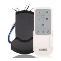
Place receiver into hanger bracket with the flat side facing the ceiling.

Connect Motor Wires

Connect fan wires (WHITE, BLACK, BLUE) to corresponding receiver wires.

Connect House Supply Wires

Connect outlet box wires (WHITE, BLACK) to receiver AC input (N, L).

Secure Wire Connections

Use wire nuts and electrical tape for secure splices and prevent loose strands.

Remote and Receiver Pairing

Pairing Procedure

Power off fan, turn on within 60s, hold FAN OFF button for confirmation.

Remote Control Operation

Light Control Function

Turn light on/off and adjust brightness by holding the button.

Fan Speed Adjustment

Select desired fan speed (Low, Medium, High) with dedicated buttons.

Fan Stop Function

Press the Stop button to immediately turn off the fan.

Timer Settings

Set fan to auto-off after 2, 4, or 8 hours using timer buttons.

Important Notices and Cautions

Installation Restrictions

Do not use with solid state speed/dimmer controls to avoid permanent damage.

Mounting Angle Caution

Ensure ceiling angle does not exceed 30 degrees for receiver mounting.

Smartphone App Setup and Pairing

App Download and Account Setup

Download Atmosync app from store, create or log into an account.

Device Discovery and Selection

Tap '+', select 'Lighting', then 'Ceiling Fan (Wi-Fi)' to add device.

Wi-Fi Network Configuration

Connect to a 2.4GHz Wi-Fi network and enter your Wi-Fi password.

Device Pairing Process

Follow app instructions: power cycle fan, confirm indicator status.

Connection Confirmation

Wait for device connection and verify it shows as 'AtmoSync AC'.

Voice Assistant Setup

Link device to Google Assistant or Alexa via 'Third-party Control' section.

Related product manuals