EasyManua.ls Logo

andrews 65/173 - User Manual

andrews 65/173
96 pages
Print Icon
To Next Page IconTo Next Page
Loading...
Working towards
a cleaner future
Gas Fired Storage
Water Heaters
Installation guide, operation
and service manual
This manual must be kept with the appliance October 2013
Part No E132
Natural Gas
HI-FLO RANGE
Models 32/143, 65/173, 81/264, 62/341, 54/418, 54/440
Permanent Pilot, Auto Ignition with Flue Damper ‘E’/‘F’ Series, ‘G’ Series
STANDARD RANGE
Models 24/39, 32/40, 40/61, 63/62, and 84/87
Permanent Pilot, Auto Ignition

Other manuals for andrews 65/173

Question and Answer IconNeed help?

Do you have a question about the andrews 65/173 and is the answer not in the manual?

Summary

Gas Fired Storage Water Heaters

Hi-Flo and Standard Range Overview

Introduces the two main product ranges covered in the manual.

SECTION 1 GENERAL AND SAFETY INFORMATION

General Information and Installation Requirements

Overview of the heater and essential installation prerequisites.

British Standards and Codes of Practice

Lists relevant industry standards and codes for installation.

SECTION 1 GENERAL AND SAFETY INFORMATION (Continued)

Health and Safety Regulations

Details compliance with health and safety legislation.

Legionella Prevention and Control

Discusses measures to prevent Legionella bacteria growth.

SECTION 2 TECHNICAL DATA

Standard Range Technical Specifications

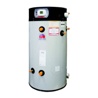
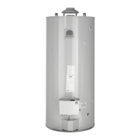
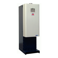
Provides detailed specifications for the standard range models.

SECTION 2 TECHNICAL DATA (Continued)

Hi-Flo Range Technical Specifications

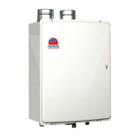
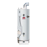
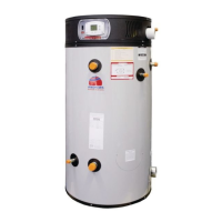
Provides detailed specifications for the Hi-Flo range models.

SECTION 3 INSTALLATION

Installation Introduction and Legal Requirements

Outlines legal requirements and an introduction to the installation process.

Draught Diverter Assembly

Instructions for assembling the draught diverter component.

Location Guidelines

Advises on suitable locations for heater installation.

SECTION 3 INSTALLATION (Continued)

Location Requirements

Further specifies site requirements for installation.

Gas Supply Connection Procedures

Step-by-step guide for connecting the gas supply.

SECTION 3 INSTALLATION (Continued)

Electrical Supply Connections

Details how to connect the electrical supply to the unit.

SECTION 3 INSTALLATION (Continued)

Electrical Wiring Diagrams

Provides schematic diagrams for electrical wiring.

SECTION 3 INSTALLATION (Continued)

Flue System Installation Guidelines

Recommendations and standards for flue system installation.

SECTION 3 INSTALLATION (Continued)

Flue System Configurations

Illustrates different flue configurations and common practices.

SECTION 3 INSTALLATION (Continued)

Air Supply and Ventilation Requirements

Specifies minimum requirements for air supply and ventilation.

SECTION 3 INSTALLATION (Continued)

Important Air Supply and Ventilation Notes

Key considerations and warnings for air supply and ventilation.

SECTION 3 INSTALLATION (Continued)

Water Quality and Treatment Recommendations

Advice on managing water hardness and scale formation.

SECTION 3 INSTALLATION (Continued)

Water Connections: Hydrojet System

Explains the function of the Hydrojet system in water connections.

SECTION 3 INSTALLATION (Continued)

Water Connections: Vented Systems (Standard Range)

Details water connections for standard range vented systems.

SECTION 3 INSTALLATION (Continued)

Vented System Layout Diagrams (Standard Range)

Illustrates typical water service layouts for vented standard range systems.

SECTION 3 INSTALLATION (Continued)

Correx Powered Anodes Installation

Instructions for fitting the Correx powered anode system.

SECTION 3 INSTALLATION (Continued)

Correx Powered Anodes Diagrams and Parts

Diagrams and part numbers for the Correx anode kit.

SECTION 3 INSTALLATION (Continued)

Water Connections: Unvented Systems (Standard Range)

Details water connections for standard range unvented systems.

SECTION 3 INSTALLATION (Continued)

Unvented System Layout Diagrams (Standard Range)

Illustrates typical water service layouts for unvented standard range systems.

SECTION 3 INSTALLATION (Continued)

Water Connections: Vented Systems (Hi-Flo Range)

Details water connections for Hi-Flo range vented systems.

SECTION 3 INSTALLATION (Continued)

Vented System Layout Diagrams (Hi-Flo Range)

Illustrates typical water service layouts for Hi-Flo range vented systems.

SECTION 3 INSTALLATION (Continued)

Multiple Vented System Layout Diagrams (Hi-Flo Range)

Illustrates layouts for multiple Hi-Flo vented systems.

SECTION 3 INSTALLATION (Continued)

Water Connections: Unvented Systems (Hi-Flo Range)

Details water connections for Hi-Flo range unvented systems.

SECTION 3 INSTALLATION (Continued)

Unvented System Layout Diagrams (Hi-Flo Range - Single Unit)

Illustrates layouts for single Hi-Flo unvented systems.

SECTION 3 INSTALLATION (Continued)

Multiple Unvented System Layout Diagrams (Hi-Flo Range)

Illustrates layouts for multiple Hi-Flo unvented systems.

SECTION 4 COMMISSIONING

Standard Range Permanent Pilot Models Commissioning

Step-by-step guide for commissioning standard range pilot models.

SECTION 4 COMMISSIONING (Continued)

Standard Range Permanent Pilot Models: Burner Pressure Check

Procedure for checking burner pressure on standard pilot models.

SECTION 4 COMMISSIONING (Continued)

Hi-Flo Range Permanent Pilot Models Commissioning

Step-by-step guide for commissioning Hi-Flo range pilot models.

SECTION 4 COMMISSIONING (Continued)

Hi-Flo Range Permanent Pilot Models: Burner Pressure Check

Procedure for checking burner pressure on Hi-Flo pilot models.

SECTION 4 COMMISSIONING (Continued)

Standard Range Auto Ignition Models Commissioning

Step-by-step guide for commissioning standard range auto ignition models.

SECTION 4 COMMISSIONING (Continued)

Standard Range Auto Ignition Models: Burner Pressure Check

Procedure for checking burner pressure on standard auto ignition models.

SECTION 4 COMMISSIONING (Continued)

Hi-Flo Range Auto Ignition Models Commissioning

Step-by-step guide for commissioning Hi-Flo range auto ignition models.

SECTION 4 COMMISSIONING (Continued)

Hi-Flo Range Permanent Pilot Models: Pilot Flame Check

How to check the pilot flame on Hi-Flo permanent pilot models.

Instructing the User on Operation

Guidance on explaining operation to the end-user.

SECTION 4 COMMISSIONING (Continued)

User Safety Guide for Lighting

Essential safety precautions before lighting the appliance.

SECTION 5 OPERATION

Standard Range Operation

General operating procedures for standard range models.

Hi-Flo Range Permanent Pilot Operation

Operating sequence for Hi-Flo permanent pilot models.

Auto Ignition Models Operation

Operating sequence for auto ignition models.

ECO and Temperature Stratification

Explanation of Energy Cut-Off and temperature stacking phenomena.

SECTION 6 SERVICING

Introduction to Servicing

General advice and frequency for servicing the heater.

Pre-Service Operations

Steps to take before commencing any servicing tasks.

Standard Range Burner Assembly Servicing

Detailed instructions for servicing the burner assembly on standard models.

SECTION 6 SERVICING (Continued)

Hi-Flo Range Burner Assembly Servicing

Detailed instructions for servicing the burner assembly on Hi-Flo models.

Gas Control Valve Servicing

Guidance on checking and servicing the gas control valve.

Flue Ways Servicing (Standard Range)

Procedure for checking and cleaning flue ways on standard models.

SECTION 6 SERVICING (Continued)

Flue Ways Servicing (Hi-Flo Range)

Procedure for checking and cleaning flue ways on Hi-Flo models.

Storage Vessel Cleaning and Descaling

Instructions for cleaning the storage vessel and descaling procedures.

Magnesium Anode Maintenance

Guidance on inspecting and replacing magnesium anodes.

Hi-Flo Range Safety Valve Servicing

Instructions for servicing the safety valve on Hi-Flo models.

SECTION 7 REPLACING COMPONENTS (Hi-Flo Range)

Replacing the Gas Control Valve

Detailed steps for replacing the gas control valve on Hi-Flo models.

Replacing the Control Thermostat

Instructions for replacing the control thermostat and limit sensor.

SECTION 7 REPLACING COMPONENTS (Hi-Flo Range) (Continued)

Replacing Thermopile, Pilot, and Burner

Steps for replacing the thermopile, pilot assembly, and burner.

Replacing the Burner Assembly

Specific instructions for replacing the burner assembly.

SECTION 8 FAULT FINDING

Permanent Pilot Models Faults

Common faults and troubleshooting steps for pilot models.

SECTION 8 FAULT FINDING (Continued)

All Models Faults and Troubleshooting

Common issues affecting all models and their solutions.

SECTION 8 FAULT FINDING (Continued)

Auto Ignition Models Faults (Standard & Hi-Flo)

Faults specific to auto ignition models.

Checking Correx Anodes

How to check the status and function of Correx anodes.

SECTION 9 PARTS LIST AND ILLUSTRATIONS

Standard Models Parts Diagrams (24;29-63;62)

Exploded diagrams showing parts for standard models.

Standard Model 84;87 Parts Diagram

Exploded diagram showing parts for the standard model 84/87.

SECTION 9 PARTS LIST AND ILLUSTRATIONS (Continued)

Standard Models Detailed Parts List

Comprehensive list of part numbers and descriptions for standard models.

SECTION 9 PARTS LIST AND ILLUSTRATIONS (Continued)

Hi-Flo Model 32;143 Parts Diagram

Exploded diagram showing parts for the Hi-Flo model 32/143.

Hi-Flo Models 65;173 & 81;264 Parts Diagram

Exploded diagrams showing parts for Hi-Flo models 65/173 and 81/264.

SECTION 9 PARTS LIST AND ILLUSTRATIONS (Continued)

Hi-Flo Models Detailed Parts List

Comprehensive list of part numbers and descriptions for Hi-Flo models.

SECTION 9 PARTS LIST AND ILLUSTRATIONS (Continued)

Hi-Flo Models 62;341 & 54;418;440 Parts Diagram

Exploded diagrams showing parts for Hi-Flo models 62/341 and 54/418/440.

SECTION 9 PARTS LIST AND ILLUSTRATIONS (Continued)

Hi-Flo Models Detailed Parts List (Continued)

Further comprehensive list of part numbers for Hi-Flo models.

SECTION 9 PARTS LIST AND ILLUSTRATIONS (Continued)

Unvented Systems Kits Parts Diagrams

Diagrams showing components of unvented systems kits.

SECTION 9 PARTS LIST AND ILLUSTRATIONS (Continued)

Unvented Systems Kits Detailed Parts List

Detailed list of parts for unvented systems kits.

SECTION 9 PARTS LIST AND ILLUSTRATIONS (Continued)

24 Volt Auto System Kits Parts Diagrams

Diagrams showing components of 24-volt auto system kits.

SECTION 9 PARTS LIST AND ILLUSTRATIONS (Continued)

24 Volt Auto System Kits Detailed Parts List

Detailed list of parts for 24-volt auto system kits.

APPENDICES: HI-FLO AUTO IGNITION G SERIES ADDENDUM

Honeywell Integrated Controls System Features

Highlights features of the Honeywell control system for Hi-Flo G series.

APPENDICES (Continued)

Technical Specifications

Lists overall technical specifications of the water heater system.

APPENDICES (Continued)

Sequence of Operation and Lockout Conditions

Explains the operational sequence and how lockout conditions are managed.

APPENDICES (Continued)

Troubleshooting: Blank Display

Steps to diagnose and resolve issues with a blank display.

APPENDICES (Continued)

Troubleshooting Flowchart

A visual flowchart for diagnosing operational problems.

APPENDICES (Continued)

Accessing Service Mode

Guide for service personnel to enter and navigate the service mode.

APPENDICES (Continued)

Service Mode Display Options

Explains various display options available within the service mode.

APPENDICES (Continued)

Service Mode Display Options (Continued)

Further details on accessing and interpreting service mode displays.

APPENDICES (Continued)

Software Version and Error Code History

How to view software version and past error codes.

APPENDICES (Continued)

Changing Maximum Setpoint

Procedure for adjusting the maximum allowable temperature setpoint.

APPENDICES (Continued)

Exiting Service Mode and Water Temperature Display

How to exit service mode and view water temperature readings.

APPENDICES (Continued)

Flame Sense Current and Temperature Setpoint Display

How to display flame current and adjust temperature setpoint.

APPENDICES (Continued)

Changing Temperature Setpoint

Detailed steps for changing the temperature setpoint.

APPENDICES (Continued)

Changing Temperature Format (°F;°C)

Guide to changing the display format between Fahrenheit and Celsius.

APPENDICES (Continued)

Changing Temperature Format (°F;°C) (Continued)

Continued steps for changing temperature display format.

APPENDICES (Continued)

Error Codes and History Display

Information on displaying error codes and accessing historical error data.

APPENDICES (Continued)

Viewing Previous Error Codes

Step-by-step instructions for viewing past error codes.

APPENDICES (Continued)

Viewing Previous Error Codes (Continued)

Continued steps for viewing error code history.

APPENDICES (Continued)

Error Code Definitions

A comprehensive list defining all error codes and their meanings.

APPENDICES (Continued)

Resetting Lockout Conditions

Procedures for resetting soft and hard lockout conditions.

APPENDICES (Continued)

Service Procedure D24-I: Thermostat Circuit Testing

Detailed procedure for testing the thermostat circuit.

APPENDICES (Continued)

Service Procedure D24-I: Thermostat Circuit Testing (Continued)

Steps to reset the control after an overheating condition.

APPENDICES (Continued)

Service Procedure D24-I: Sensor Resistance Testing

Guide for testing sensor resistance at various temperatures.

APPENDICES (Continued)

Service Procedure D24-II: Pilot Operation Testing

Troubleshooting steps for pilot not lighting or staying lit.

APPENDICES (Continued)

Service Procedure D24-II: Pilot Inspection

How to inspect the pilot assembly and orifice for issues.

APPENDICES (Continued)

Service Procedure D24-II: Pilot Operation Testing (Continued)

Checking pilot flame sensor and microamp output.

APPENDICES (Continued)

Service Procedure D24-III: Main Burner Operation Testing

Troubleshooting steps when the main burner fails to light.

APPENDICES (Continued)

Service Procedure D24-III: Main Burner Operation Testing (Continued)

Troubleshooting main burner short cycling issues.

APPENDICES (Continued)

Service Procedure D24-IV: Main Burner & Pilot Removal and Inspection

Instructions for removing and inspecting the main burner and pilot assembly.

APPENDICES (Continued)

Service Procedure D24-IV: Pilot Burner Removal and Inspection

Detailed steps for removing and inspecting the pilot burner.

APPENDICES (Continued)

Service Procedure D24-IV: Control Board Replacement

Step-by-step guide for replacing the control board.

APPENDICES (Continued)

Service Procedure D24-V: Flue Baffle Removal and Inspection

Instructions for removing and inspecting the flue baffles.

APPENDICES (Continued)

Service Procedure D24-VI: Anode Removal and Inspection

Guide for removing and inspecting anode rods.

APPENDICES (Continued)

Parts Identification Diagram

Visual representation of various parts with reference numbers.

APPENDICES (Continued)

Parts List Cross-Reference

Table linking part numbers to specific models and their applications.

andrews 65/173 Specifications

General IconGeneral
Brandandrews
Model65/173
CategoryWater Heater
LanguageEnglish

Related product manuals