Chapter 6 — Removal and Replacement Procedures 6-2 Power Meter Disassembly
ML248xx, ML249xA MM PN: 13000-00164 Rev. K 6-5
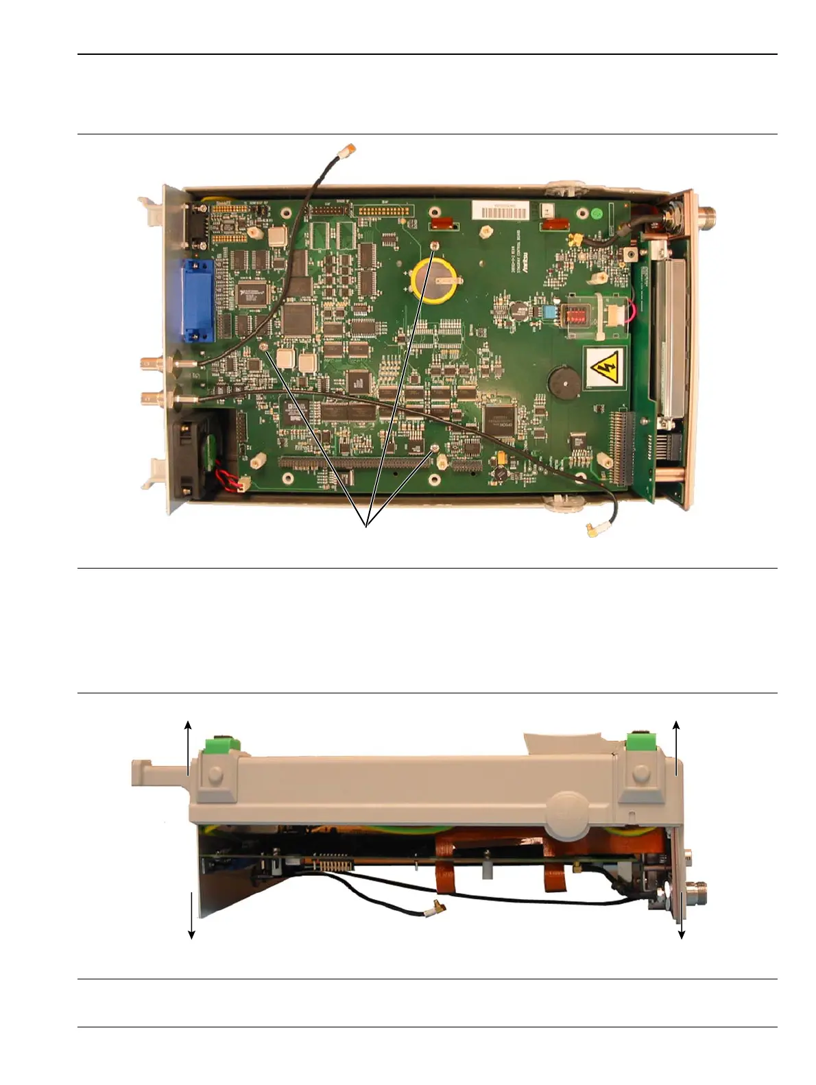
Main Control PCB Removal
1. Remove the three screws that secure the control PCB to the lower case as shown in Figure 6-4
2. Turn the unit over so that it rests on the front panel and the rear panel. Press down on the rear panel
BNC connectors and lift up the lower case. This will break the rear panel free from the lower case.
DO NOT attempt to remove the PCB yet.
3. Press down on the front panel from the lower case. DO NOT attempt to remove the front panel yet.
Figure 6-4. Main Control PCB Screw Removal
Figure 6-5. Separating Rear Panel From Lower Case
Control PCB
Mounting Screws
Press Down
Rear Panel
Press Down
Front Panel
Pull Case Up Pull Case Up

 Loading...