Chapter 7 — Firmware Updates 7-4 Serial Interface Cable
ML248xx, ML249xA MM PN: 13000-00164 Rev. K 7-3
7-4 Serial Interface Cable
The 9-pin null-modem serial interface cable necessary for upgrading the power meter firmware is available
from the Anritsu Customer Service department.
Order Anritsu part number 2000-1544.
The cable can also be assembled from the following readily available components:
• 2 meters of 8-conductor cable (Anritsu P/N: 800-365).
• 2 each, 9-pin female D-connectors.
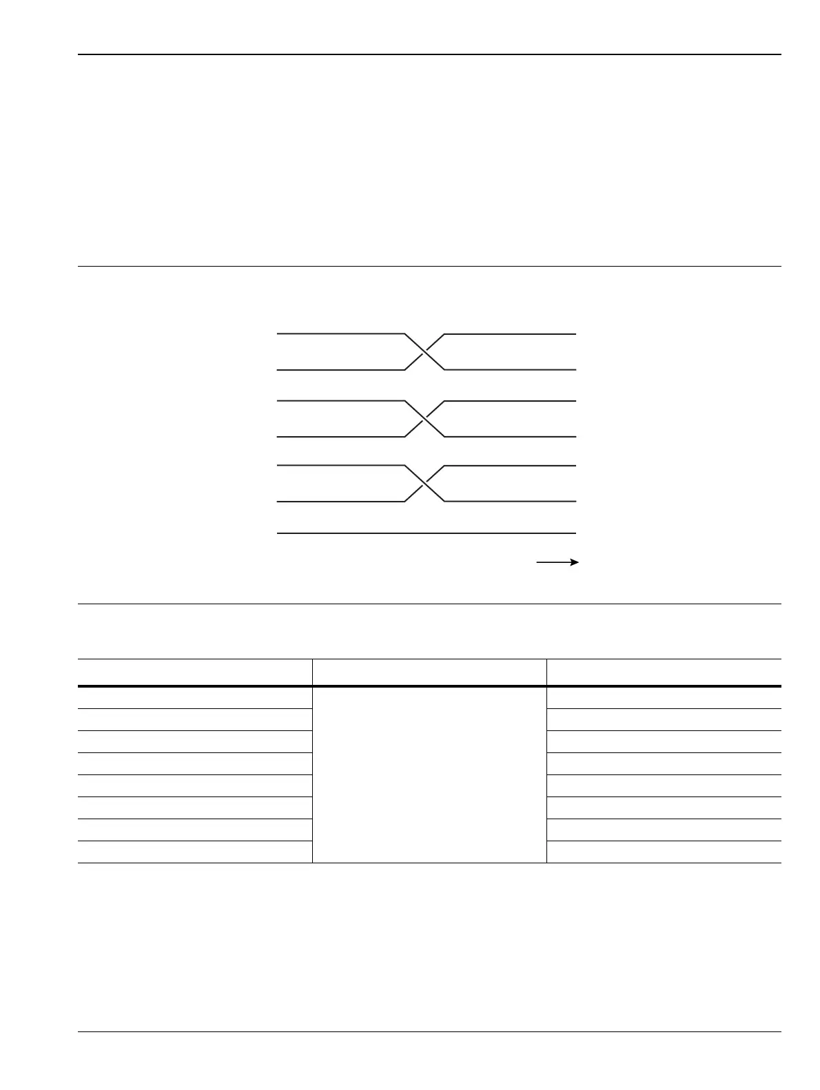
Assemble the cable according to the following connection diagram and description.
Figure 7-2. Serial Interface Cable Connections
Table 7-1. Serial Interface Cable Connections
D-Connector Number 1 Pin To D-Connector Number 2 Pin
2
Connect To:
3
3 2
4 6
5 5
6 4
7 8
8 7
– Pin 5 to Cable shield
2 RED
4 YELLOW
6 BROWN
7 WHITE
8 BLUE
5 GREEN
5
CABLE SHIELD
GREEN 5
WHITE 8
BLUE 7
YELLOW 6
BROWN 4
RED 3
ORANGE 2
Connector 1 Connector 2
3 ORANGE

 Loading...