4.6
4.64.6
4.6 FM Deviation Adjustment
FM Deviation AdjustmentFM Deviation Adjustment
FM Deviation Adjustment
4-
4-4-
4-9
99
9
4.6 FM Deviation Adjustment
After replacing the following listed MT8820A units, re-adjust the FM de-
viation character.
•
A03 AUDIO unit
•
A
2
1/A22 TDMA COM unit
•
A81/A82 LOCAL unit
(1) Setup
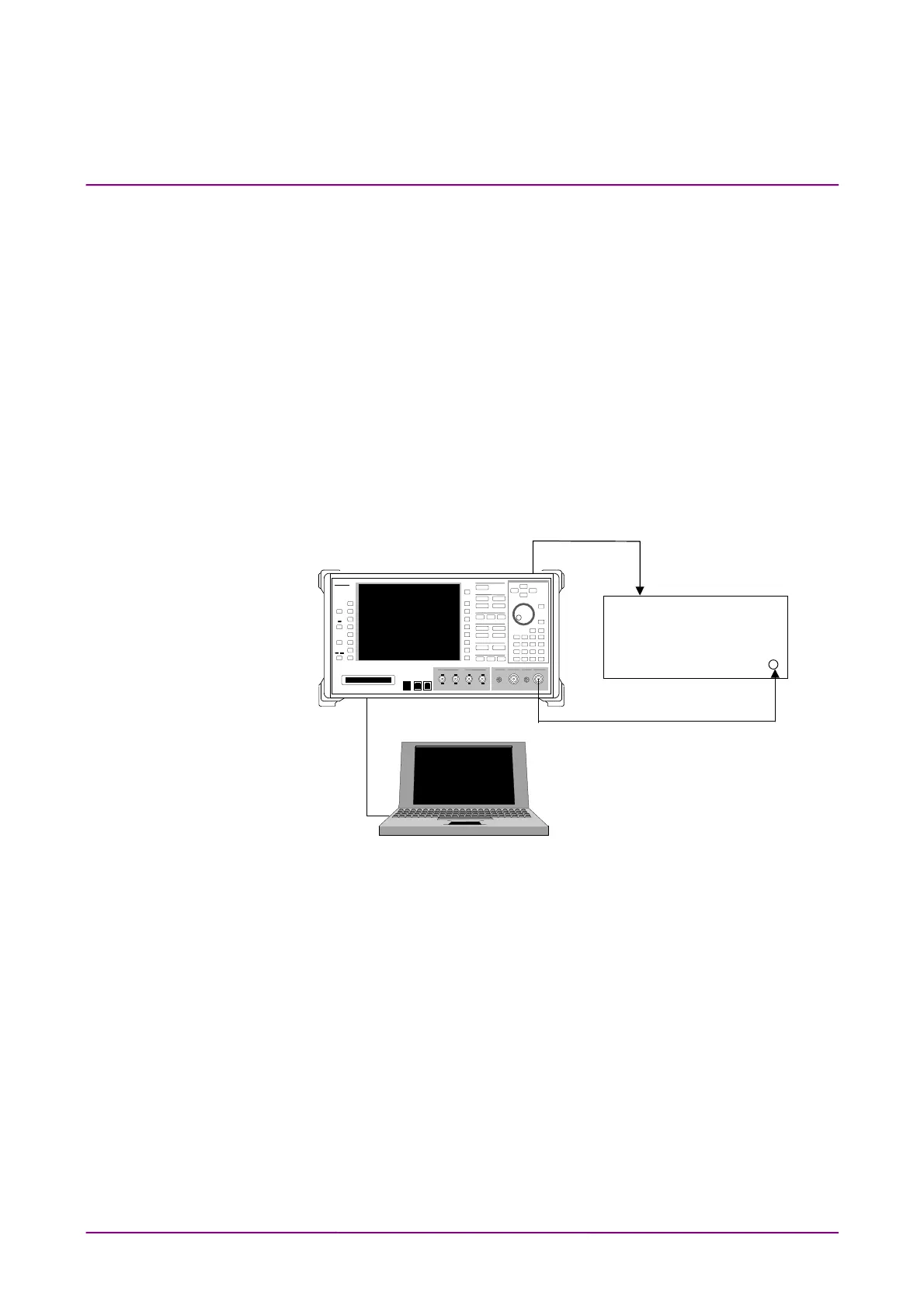
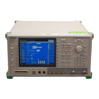
Connect the MT8820A MAIN1 Output connector to the modulation-
analyzer RF Input connector using a coaxial cable. And then, con-
nect a personal computer for GPIB control. (Figure 4-6)
10 MHz
Ref Input
8902B
Modulation Analyzer
nritsu
MT8820A
10 MHz
Buff Output
MT8820A
PC
Fig. 4-6 Setup






 To Next Page