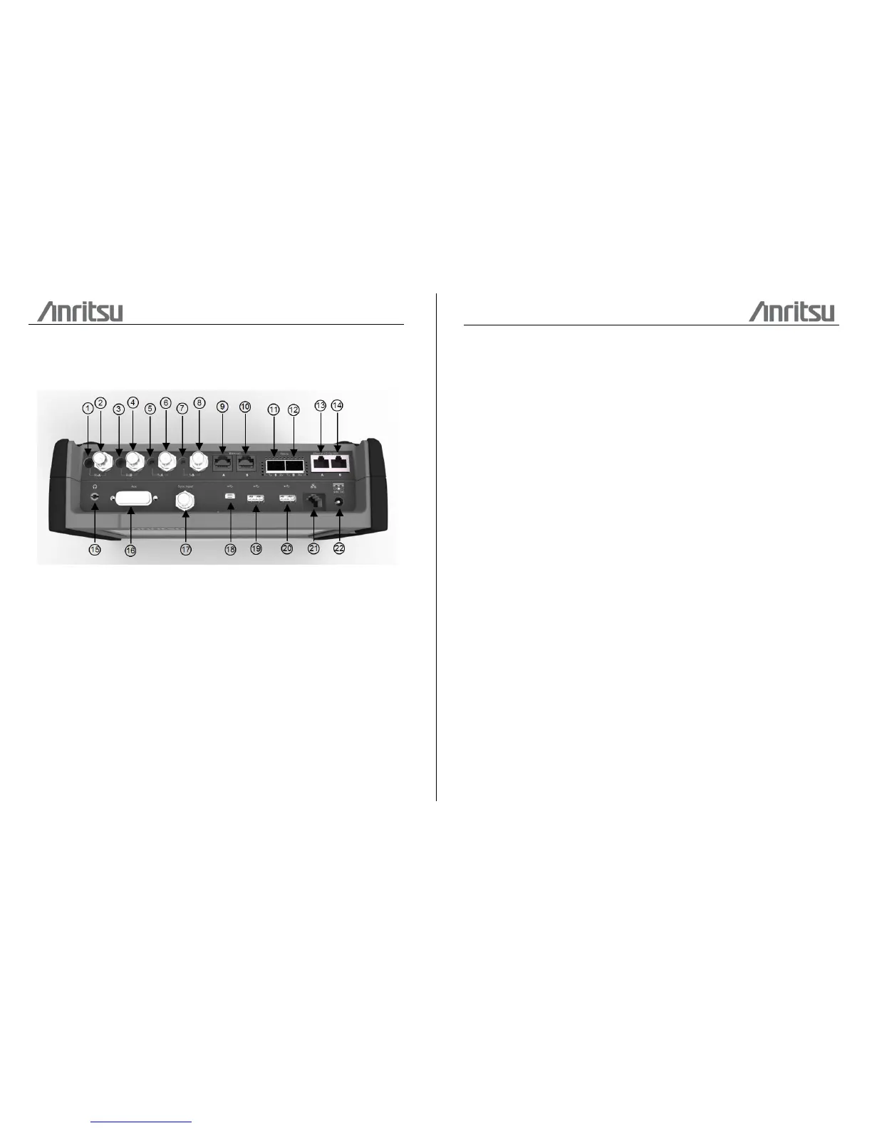
Connector Panel
All connections (both for test interfaces and for service interfaces) are placed on the
connector panel of the Network Master.
From 1 to 14, there are to be used for the tests interfaces.
From 15 to 22, there are to be used for the service interfaces.
1. Port 1, Tx Bantam (DS1)
2. Port 1, Tx BNC (E1, E3, E4, DS3, STM-1-e, STS-3e)
3. Port 1, Rx Bantam (DS1)
4. Port 1, Rx BNC (E1, E3, E4, DS3, STM-1-e, STS-3e)
5. Port 2, Tx Bantam (DS1)
6. Port 2, Tx BNC (E1, E3, E4, DS3, STM-1-e, STS-3e)
7. Port 2, Rx Bantam (DS1)
8. Port 2, Rx BNC (E1, E3, E4, DS3, STM-1-e, STS-3e)
9. Port 1, Tx/Rx RJ48 (E1 balanced)
10. Port 2, Tx/Rx RJ48 (E1 balanced)
11. Port 1, Tx/Rx SFP/SFP+ (SDH / SONET / OTN / Ethernet optical)
12. Port 2, Tx/Rx SFP/SFP+ (SDH / SONET / OTN / Ethernet optical)
13. Port 1, Tx/Rx RJ45 (Ethernet electrical)
14. Port 2, Tx/Rx RJ45 (Ethernet electrical)
15. Audio 19. USB A
16. AUX 20. USB A
17. Clock input 21. Ethernet service interface
18. USB B 22. DC input (18 VDC)





 To Next Page