4
Installation
1. Disconnect the power cord from your old power supply.
2. Open your computer case. Follow the directions provided in your case manual.
3. Disconnect all power connectors from the motherboard and from the peripherals devices
such as case fans, hard drives, optical drives, floppy drives, etc.
4. Remove the existing power supply from your computer case and replace it with your new
Antec power supply.
5. Note (NOT applicable to models designed for the European Union): Before you install
your new power supply, check the red power supply voltage switch setting. It should match
your local power voltage (115V for North America, Japan, etc., 230V for Europe, South
East Asia, and many other countries). Change the voltage setting if necessary. If you use
the wrong voltage setting, you could damage your system and void your warranty.
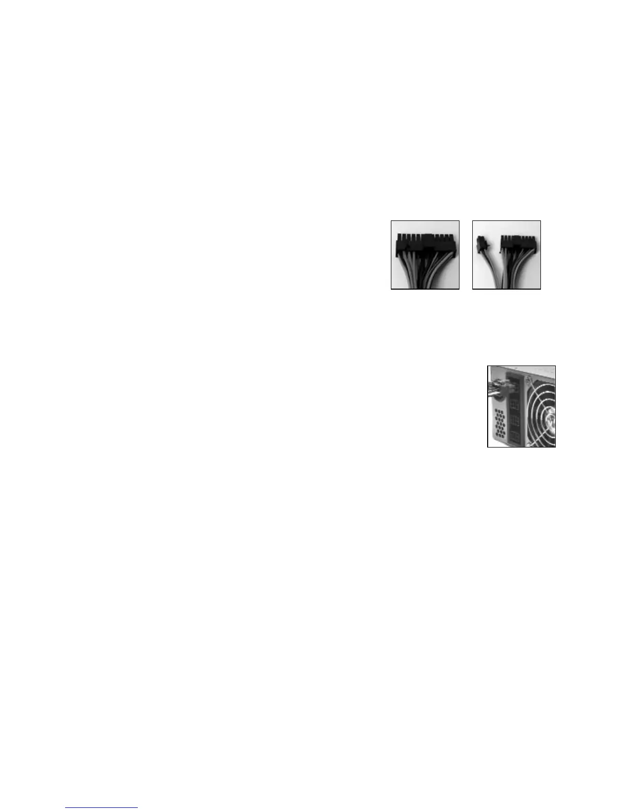
6. Connect the 24-pin Main Power Connector and the
4-pin +12V connector to your motherboard as
needed. If your motherboard uses a 20-pin
connector, detach the 4-pin attachment on the
24-pin power connector (see Pictures 2 and Picture 3).
7. In the package, you'll find a set of power
supply-to-Molex connectors. (One of the PSU to
Molex connectors is shorter than the others. We
recommend connecting it to CD-ROMs.)
Connect one of the 6-pin connectors to any of the
6-pin sockets on the power supply. (See Picture 4).
8. Note: One of the PSU-to-Molex connectors is shorter than the others.
9. If you have a SATA drive: In the package, you'll find a power supply-to-SATA
connector. Connect the 6-pin connector to any of the 6-pin sockets on the
power supply.
10. Connect the SATA connector to your SATA drives. Repeat as necessary.
11. In the package, you'll find a PCI Express graphic card connector. It's the only
6-pin connector with 3 yellow wires and 3 black ones. Connect the 6-pin PCI
Express connector to your PCI Express graphic card if needed. Note: Please consult the
user manual supplied with your PCI Express graphic card for detailed usage instructions.
12. Optional: If you'd like to monitor the speed of the power supply fan, connect the 3-pin fan
signal connector to one of the fan connectors on your motherboard. Note: You don't need
to connect the fan signal connector in order for the power supply to work.
13. Connect the power cord to the power supply.
Note: If your motherboard requires a 6-pin AUX Power Connector, please contact Antec
Customer Service at 800-22ANTEC (North America) or +31 (0)10 462-2060 (Europe) to
purchase the optional AUX Power Connector.
Additional Connectors
The spare connectors are not intended to add additional length to the cable sets, but rather to
add additional connectors to the existing cables (see Picture 5 and Picture 6).
To add a spare Molex or SATA connector to an existing cable:
1. Measure and mark the desired position on the wire set that you want to add the additional
connector to.
2. Remove the wire set from the power supply and place it on a flat, firm surface.
3. Place the additional connector under the wires with the cap open as shown. (See Picture 5
(Molex) and Picture 6 (SATA).)
Picture 2
Picture 3
For 24-pin
motherboards
For 20-pin
motherboards
Picture 4