1. Cut off one of the connectors on a standard Cat5e or Cat6 Ethernet cable.
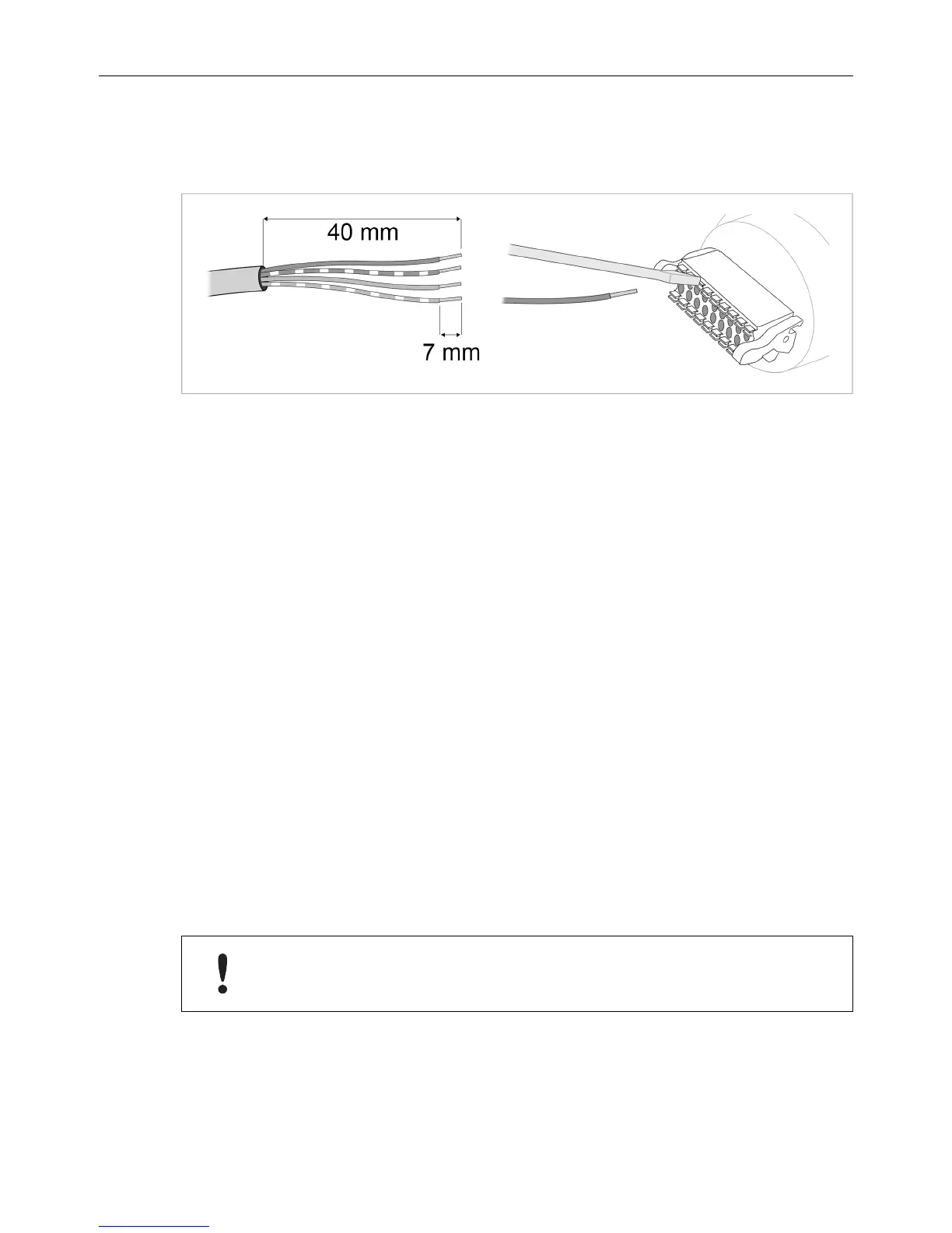
2. Strip off about 40 mm (1½ inch) of the cable jacket and untwist the orange,
orange/white, green and green/white wires. The other wires will not be used.
3. Strip off about 7 mm (¼ inch) of the isolation on each wire.
4. Push the pin spring release next to each socket on the connector and insert
the correct wire end according to 18–pin Connector, p. 7.
Connect the wires from the power supply to the connector in the same way as
the Ethernet wiring. Make sure that polarity is not reversed.
RJ-45 Adapter
An Ethernet adapter with an RJ45 female connector can be ordered as an
accessory. Please contact your sales representative for more information.
2.6 Digital Input
The digital input can be used for additional functionality with advanced
configurations and to reset the unit. For more information please refer to the
Anybus Wireless Bolt/Bridge II AT Reference Guide.
If voltage is applied to the digital input for more that 10 seconds the unit
will be reset to factory defaults.
 Loading...
