The Anywave MHPTV (Granite) TV Transmitter is a robust system designed for LPTV operations, offering a comprehensive solution for broadcasting. This Quick Start Guide provides essential instructions for safe setup and initial operation, emphasizing the need for trained and qualified personnel for installation, maintenance, and service.
Function Description:
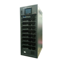
The MHPTV system is a high-level television transmitter that includes an Exciter, a Controller with a built-in preamp, multiple Power Amplifiers (ranging from 1 to 8 PAs), an input Splitter, an output Combiner, and an optional Band Pass (mask) Filter. The system is designed for both single and dual exciter configurations. The Exciter is pre-configured at the factory to the desired channel frequency, and the entire TX system, including the RF system, is tested at full power into a load. All operating parameters are optimized, and power meters for Forward, Reflected, and Reject load are calibrated. Linear and Nonlinear pre-correction are performed and stored in the Exciter's non-volatile memory. A Factory Test Report is provided with each system, detailing full power operating parameters and performance. The transmitter undergoes a 24-hour burn-in period before shipment.
The Controller serves as the central interface for monitoring and control, featuring a touchscreen LCD that displays real-time system parameters such as Forward (FWD), Reflected (REFL), and Reject Load (REJT) output power in Watts. It also provides access to Exciter settings, including frequency and drive level. The system supports Automatic Gain Control (AGC) to maintain a stable output power level. For dual exciter configurations, the Controller facilitates exciter switchover, ensuring redundancy and continuous operation.
Important Technical Specifications:
The MHPTV (Granite) Doherty (888E) series offers various power configurations with corresponding AC power requirements, dimensions, and weights.
240VAC Single-phase (L1, L2, GND):
- 1100W (ATSC), 1PA:
- Consumption: 3110W
- Breaker: 20A, 2-pole, gauge 12 wire
- Current Draw: 13.0A/phase
- Weight: 400 lbs.
- Dimensions: 1358H x 850D x 725W (mm)
- 2200W (ATSC), 2PA:
- Consumption: 6220W
- Breaker: 40A, 2-pole, gauge 8 wire
- Current Draw: 25.9A/phase
- Weight: 520 lbs.
- Dimensions: 1358H x 850D x 725W (mm)
- 3300W (ATSC), 3PA:
- Consumption: 9330W
- Breaker: 50A, 2-pole, gauge 6 wire
- Current Draw: 38.9A/phase
- Weight: 700 lbs.
- Dimensions: 1794H x 1100D x 725W (mm)
- 4400W (ATSC), 4PA:
- Consumption: N/A
- Breaker: N/A
- Current Draw: N/A
- Weight: 810 lbs.
- Dimensions: 1794H x 1100D x 725W (mm)
- 5500W (ATSC), 5PA:
- Consumption: N/A
- Breaker: N/A
- Current Draw: N/A
- Weight: 920 lbs.
- Dimensions: 1794H x 1100D x 725W (mm)
- 6600W (ATSC), 6PA:
- Consumption: N/A
- Breaker: N/A
- Current Draw: N/A
- Weight: 1060 lbs.
- Dimensions: 2063H x 1100D x 725W (mm)
- 8800W (ATSC), 8PA:
- Consumption: N/A
- Breaker: N/A
- Current Draw: N/A
- Weight: 1280 lbs.
- Dimensions: 2063H x 1100D x 725W (mm)
208VAC Three-phase (L1, L2, L3, GND) Delta:
- 1100W (ATSC), 1PA:
- Consumption: 3110W
- Breaker: 15A, 3-pole, gauge 14 wire
- Current Draw: 8.7A/phase
- 2200W (ATSC), 2PA:
- Consumption: 6220W
- Breaker: 30A, 3-pole, gauge 10 wire
- Current Draw: 17.3A/phase
- 3300W (ATSC), 3PA:
- Consumption: 9330W
- Breaker: 40A, 3-pole, gauge 8 wire
- Current Draw: 26.0A/phase
- 4400W (ATSC), 4PA:
- Consumption: 12440W
- Breaker: 50A, 3-pole, gauge 6 wire
- Current Draw: 34.6A/phase
- 5500W (ATSC), 5PA:
- Consumption: 15560W
- Breaker: 60A, 3-pole, gauge 6 wire
- Current Draw: 43.2A/phase
- 6600W (ATSC), 6PA:
- Consumption: 18670W
- Breaker: 70A, 3-pole, gauge 4 wire
- Current Draw: 51.9A/phase
- 8800W (ATSC), 8PA:
- Consumption: 24890W
- Breaker: 100A, 3-pole, gauge 2 wire
- Current Draw: 69.2A/phase
The cabinet dimensions for the 3-PA MHPTV system are 1794H x 1100D x 725W (mm). The Band Pass Filter (BPF) may be mounted on top or on the side of the TX cabinet.
Usage Features:
- Unpacking and Inspection: Users are instructed to carefully unpack, visually inspect for shipping damage, notify Anywave if damage occurs, and retain all original shipping materials. The Packing Check List should be referenced to verify all components have been received.
- RF System Connections: The TX cabinet should be positioned, and the RF system connected to the antenna feed or a suitable station load. If a BPF is purchased, it will be installed either on top of the TX cabinet or on the floor, depending on dimensions and order specifications. Connections include the 90° Elbow between the TX output stack and the BPF Input, and directional couplers. Feedback sample cables (2 x 20dB attenuators) are connected to the Before and After 50dB Directional Couplers and then to the BNC connectors on the top of the cabinet.
- TS Input Stream Connection: The 19.39 MBPS TS input stream is connected to the Exciter's TS IN 1 BNC connector using a 75ohm cable. For redundant TS inputs, the TS IN 2 BNC connector is used. The Exciter's front panel LEDs (TS1/TS2) indicate a valid input stream.
- AC Mains Connections: A licensed Electrician is required to connect the AC mains power cable from the station's electrical panel to the terminal block inside the TX AC Mains Distribution compartment, adhering to local electrical and building codes. The Main Breaker on the lower left front of the TX must be OFF during electrical work. Wiring diagrams are provided for 1-PA, 2-PA, 3-PA, 4-PA, 5-PA, 6-PA, and 8-PA systems for both 240VAC single-phase and 208VAC three-phase configurations.
- Initial Turn On:
- Turn ON the AC Main Breaker; the AC Mains LED will illuminate, and PA fans will rev up briefly before ramping down.
- The Controller's HOME screen will display FWD, REFL, and REJT power.
- Check Exciter settings, including operating frequency (Exciter FREQ submenu) and drive level (Exciter RF submenu, set to -25dBm initially).
- Slowly increase the FWD System power by raising the Exciter's POWER setting, monitoring FWD, REFL, REJT, and VSWR values on the Controller. Ensure "RUNNING OK!" status and no alarm messages.
- Continue raising FWD power to the desired TPO, ensuring PA device currents do not exceed Factory Test Report values.
- Check SNR and Shoulder (LIMD and UIMD) RF performance via the Controller or Exciter's web interface.
- Engage TX AGC by navigating to the AGC screen on the Controller, setting the AGC Target FWD power, and pressing the AGC button.
- For dual exciter configurations, test switchover by selecting EXCITER B on the Controller.
- Output Power Adjustment: The TX output power level can be adjusted by modifying the AGC target power setting under the Controller Config →AGC button, or by disabling Controller AGC and adjusting the Exciter output drive.
- Remote Monitoring and Control: The Transmitter Control Module (default IP: 192.168.1.210), Exciter (default IP: 192.168.1.143), and PA drawers (default IP: 192.168.1.200) can be networked for remote monitoring. IP addresses are user-configurable. To enable remote control, the Transmitter and Exciter must be set to REMOTE mode via their respective user interfaces.
Maintenance Features:
- Safety Warnings: The manual includes prominent warnings about electric shock hazards, emphasizing that only trained personnel should service the equipment. It stresses the dangers of high voltages, currents, and RF energy, and the importance of disconnecting power before removing covers.
- Grounding: Proper bonding of the transmitter cabinet to the building's lightning protective ground and a good RF ground (typically with a copper strap) is crucial to prevent damage and avoid voiding the warranty.
- Troubleshooting: The Controller's HOME screen displays status messages and alarms. In case of an alarm, users are directed to the Troubleshooting section of the transmitter User Manual for error explanations and corrective steps.
- Corrections: Linear and Non-Linear corrections are factory-optimized for the TX's rated TPO. If operating at a lower TPO or if re-running corrections is desired, users should consult the "Running Corrections" section of the transmitter User Manual.
- Documentation: The shipment includes a Packing Checklist, Transmitter Factory Test Report, MHPTV TX Quick Start Guide, and MHPTV TX and Exciter User Manuals, all of which are essential for reference and maintenance.
- Technical Support: Anywave provides technical support and troubleshooting assistance during normal business hours and emergency support after hours. Users are required to provide the Serial Number and Sales Order number for service requests.
- Returns and Exchanges: Written approval and a Return Material Authorization (RMA) number are required for equipment returns, obtained by contacting the Anywave Service Department with the Sales Order number and Serial Number(s).