MHPTV TX Quick Start Guide
MHPTV-QSG-DOC-V1.1, 12/05/2018 Page 15 of 37
Connect the After-filter Directional Coupler to the output of the BPF on one side
and then to the 1 5/8 or 3 1/8 slip-on flange adapter on the other side (not shown in
the photo above). This standard 1 5/8 or 3 1/8 EIA flanged output will then need to
be connected to your Antenna transmission line (please note: If your Antenna feed
is other than 1 5/8 EIA or 3 1/8 flanged, then you will need to provide whatever
adapter hardware necessary to facilitate this connection to your Antenna line).
Please be sure to install the Before and After BPF Directional Couplers in the
correct positions and orientation. Incorrect operation of the TX system may result
if these directional couplers are not installed in the proper locations with the
proper orientation as labeled.
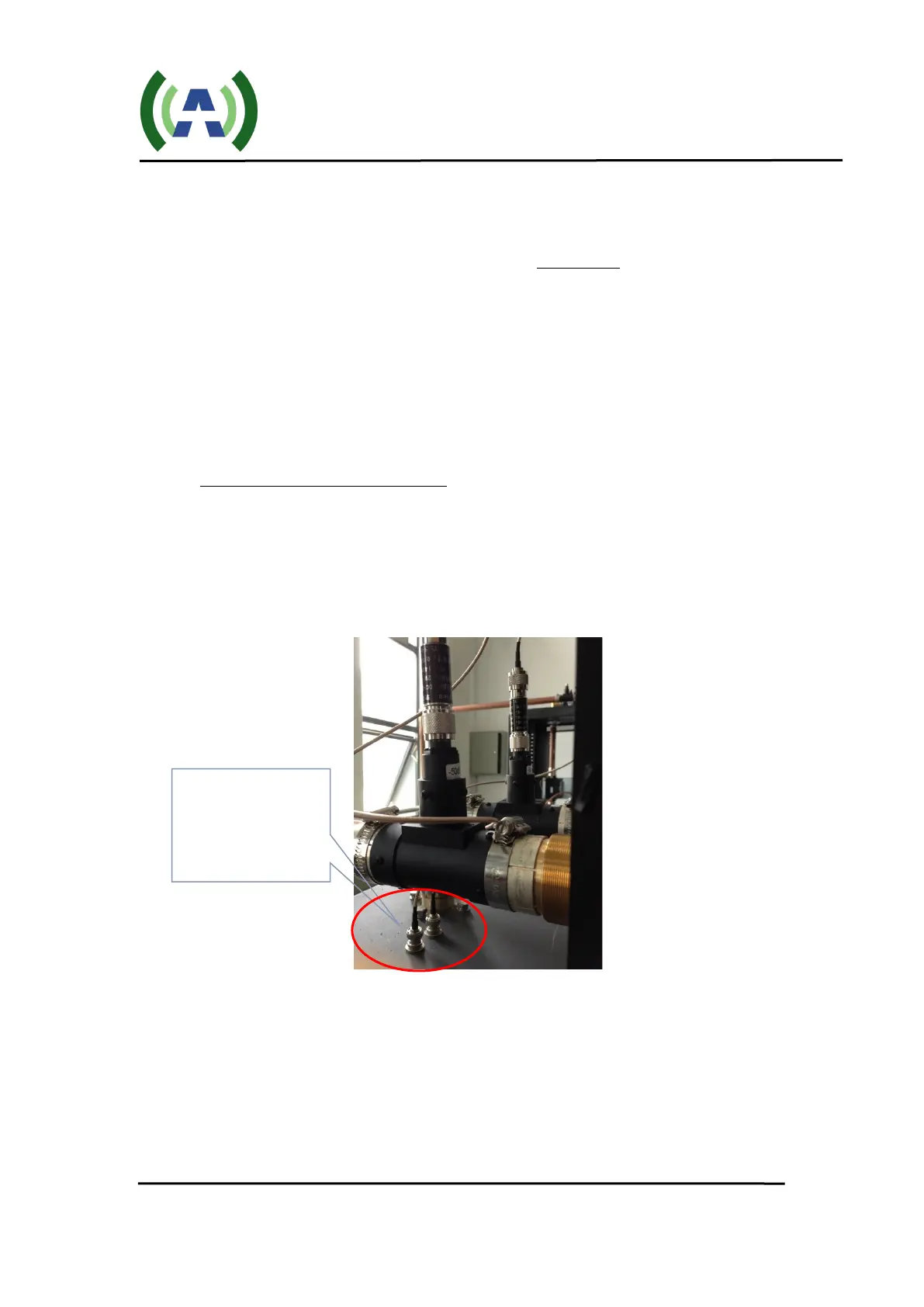
3. Connect Feedback sample cables
Connect the 2 x 20dB attenuators to the Before and After 50dB Directional
Couplers and then connect these attenuators to the Before and After filter feedback
BNC connectors located on the top of the cabinet with the cables provided (as
shown below). As a check, verify the Before and After samples are properly
connected to the respective inputs on the Exciter inside the cabinet.
7 TS Input Stream Connection
With the RF output connections properly made, the next step is to connect your
19.39 MBPS TS input stream to the Exciter inside the TX cabinet. Using a 75ohm cable,
connect your ASI input stream to the TS IN 1 BNC connector on the rear panel of the
Exciter (as shown below). If you have more than one TS (multiple STLs, etc.) connect
your redundant TS input to the TS IN 2 BNC connector.
3 – Connect
Feedback sample
cables