10
4-20
current signal 4 ÷
20 mA
0-20
current signal 0 ÷
20 mA
0-10
voltage signal 0 ÷ 10 V
0-60
voltage signal 0 ÷
60 mV
rES
resistance signal 0 ÷
2,500 Ω
rEMo
remote input from the RS485 or PRG port, chapter 16, Table 16.6
1: FiLt filtration (1)
1 ÷
20
digital filtration of measurements (response time)
5
2: dot
position of the
point/resolution
0
no point (2) or 1°C for temperature
1
(0.1 °C)
1
0
.
0 (2) or resolution 0.1 °C for temperature
2
0
.
00 (2)
3
0
.
000 (2)
3: Lo1 lower limit or
bottom of the indication
range (2)
/999 ÷ 9999
indication 0/4 mA, 0 V, 0 Ω - start of the input scale (2)
/99.9 °C
/99.9 ÷ 1800 lower setting limit for the preset value of the alarm 6: Set1
4: Hi1 upper limit or
top of the indication range
/999 ÷ 9999
indication for 20 mA, 10 V, 60 mV, 2,500 Ω
scale (2)
850.0 °C
/99.9 ÷ 1800 upper setting limit for the preset value of the alarm 6: Set1
- chapter 12 (parameters insignificant to the AR500)
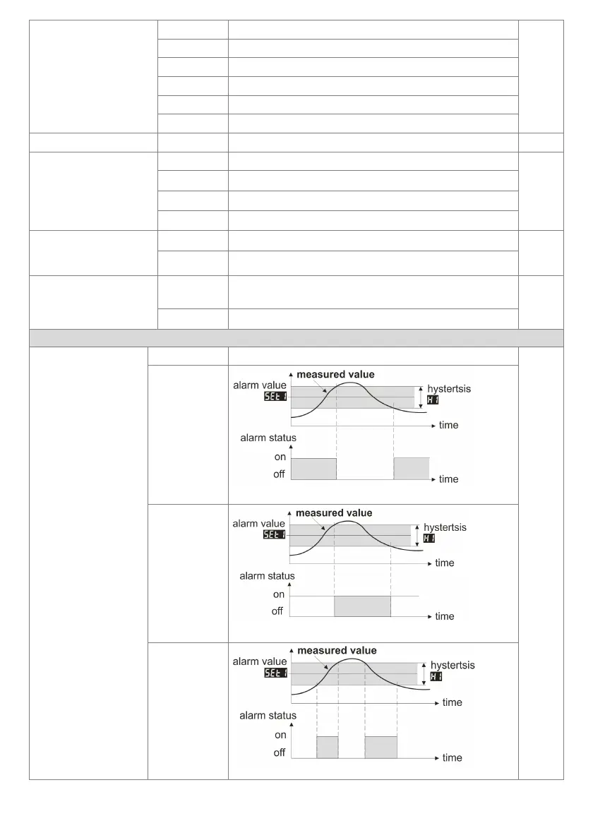
5: out1 alarm type
oFF
alarm constantly off
oFF
inu
reverse/heating
Figure 10.1. Characteristics of heating type alarm
dir
direct/cooling
Figure 10.2. Characteristics of cooling type alarm
bAon
in the band
Figure 10.3. Characteristics of alarm in the band