11
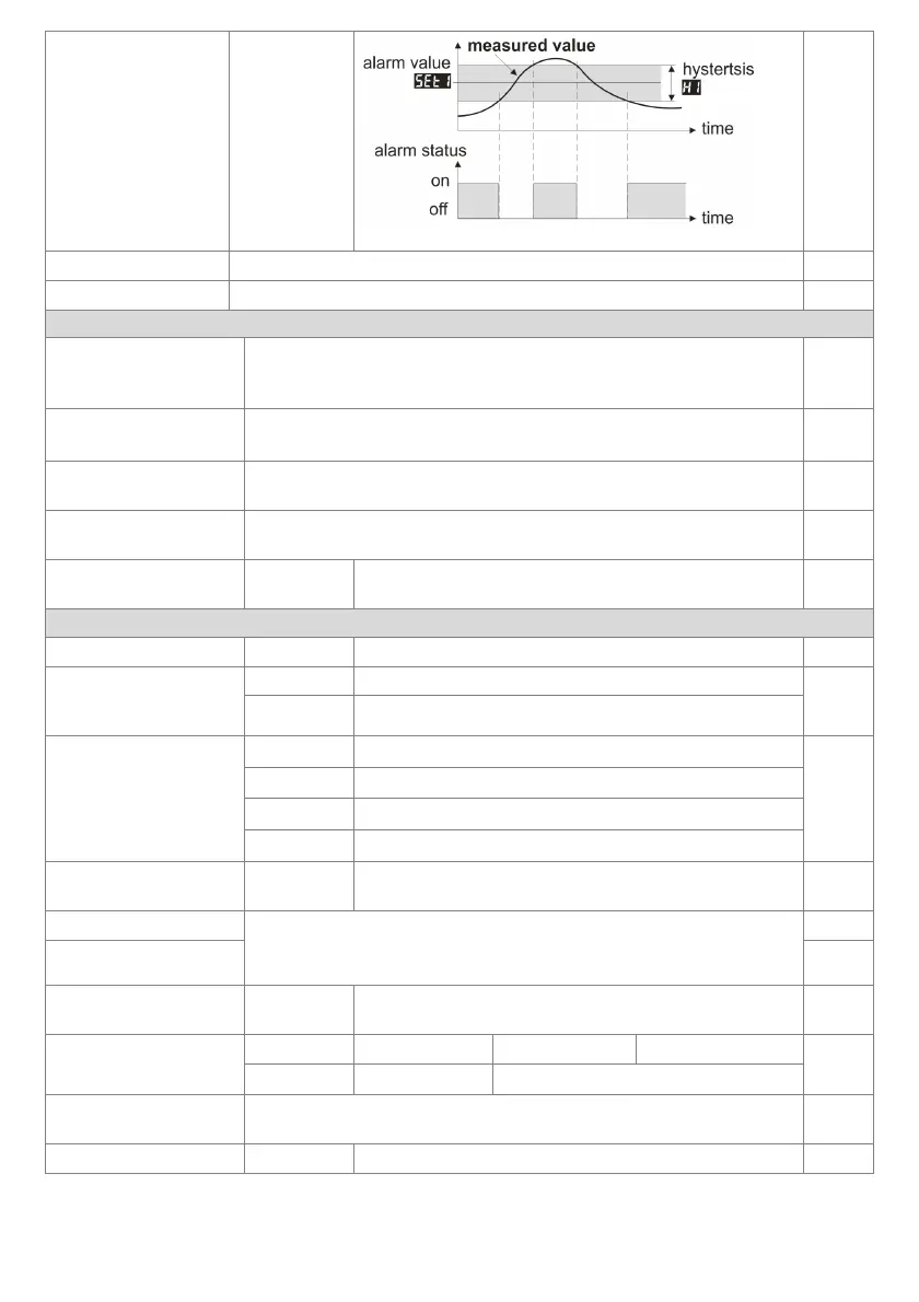
bAoF
outside of the
band
Figure 10.4. Characteristics of alarm outside of the band
6: SEt1 alarm value
changes in range 3: Lo1 ÷ 4: Hi1
100.0
°C
7: H1 alarm hysteresis
0.0 ÷ 999.9 °C or 0 ÷ 9999 units (2)
1.0
°C
ANALOG OUTPUT CONFIGURATION (
chapter 12.2, parameters insignificant to the AR500
8: AtYP type of analog
output
depending on the order code: for current output 0-20 or 4-20 mA, for voltage
output 0-10 or 2-10 V
0-20
mA
(0-10 V)
9: outA function of analog
output
oFF = off, hAnd = manual mode, rEtr = retransmission of measurement,
cont = alarm/control output, a detailed description is provided in chapter 12.2
oFF
10: A-Lo lower indication
for retransmission
start of the output scale
for output signal value 0/4 mA or 0/2 V (the parameter
is active only for measurement retransmission when 9: outA = rEtr )
0.0 °C
11: A-Hi upper indication
for retransmission
ue 20 mA or 10 V (the parameter is
active only for measurement retransmission when 9: outA = rEtr )
100.0 °C
12: HSEt preset value of
the manual mode
0 ÷ 100 %
1% step
control value for the analog output operating in the manual
mode, chapters 12.2 and 12.3
50 %
ACCESS, DISPLAY, AND COMMUNICATION OPTIONS AND OTHER CONFIGURATION PARAMETERS
13: PASS password 0000 ÷ 9999
password for the parameter configuration menu
1111
14: PPro protection of the
configuration with a
password
oFF
entry into the configuration menu is not password-protected
on
on
entry into the configuration menu is password-protected
15: Func
the BIN input function
(chapter 9, parameter
insignificant to the AR500)
nonE
the BIN input is inactive
nonE
bLoc
keypad block
hAnA
unconditional manual mode for the analog output
hoLd
stopping the display indications (HOLD function)
16: briG illumination
brightness
50 ÷ 100 %
brightness of the display, a 50% increase
100 %
17: coLo basic color GrEE = green, YELL = yellow, orAn = orange,
AMbE = amber, rEd = red, coLo = basic (only for 18: AcoL )
(18: AcoL - display color for connected alarm)
(3)
rEd
18: AcoL alarm color
AcoL
19: AddrMODBUS-RTU
address
1 ÷ 247
individual address of the device in the RS485 network
(chapter 16)
1
20: br
speed for RS485
2.4 kbit/s
4.8 kbit/s
9.6 kbit/s
19.2 kbit/s
19.2
kbit/s
38.4 kbit/s
57.6 kbit/s
115.2 kbit/s
21: cALo calibration
of the zero
zero offset for measurements: -50.0 ÷ 50.0 °C or -500 ÷ 500 units (2) 0.0 °C
22: cALG gain
85.0 ÷ 115.0 %
Slope calibration (sensitivity) for measurements
100.0 %
Notes: (1) – for FiLt = 1 the response time is equal to 0.25 s, for FiLt = 20 it is equal to at least 3 s. A higher
degree of filtration means a more "smooth" measured value and a longer response time,