Do you have a question about the APART CONCEPT1 and is the answer not in the manual?
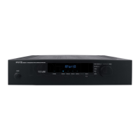
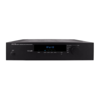
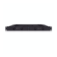
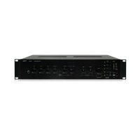
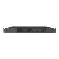
Button to turn the power of the unit on and off.
Buttons to select audio sources A through D, indicated by LEDs.
Front panel input for personal audio devices, shared with rear Source D.
Button to select basic submenus and navigate through options.
Rotary knob for adjusting main volume and other menu parameters.
Indicates unit status: lit when off by remote, flashes on data transmission.
Component that receives signals from infrared remote controls.
Dot matrix display showing current status, source, and menu information.
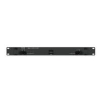
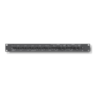
Euroblock connector for paging microphones with signal and ground connections.
Adjusts the input gain level for the microphone signal.
Adjusts the treble/bass balance of the microphone input signal.
Terminal for connecting safety ground lead or shielded cable screens.
Signal output mirroring the Line A input signal.
Stereo line inputs via standard RCA connectors.
Stereo line input via RCA connector, also available on front panel.
RCA outputs providing signal before master volume, for recording or loops.
RCA outputs providing signal after volume and limiter, for subwoofers or amps.
Switches reduce sub bass frequencies for small speakers when used with subwoofers.
Euroblock connectors for 100 Volt speaker outputs (167 ohm minimum).
Connector for optional IR remote receiver, bypasses front IR receiver.
9-pin Sub-D connector for computer or system controller connection.
Mains cable connection point. Verify mains voltage before connecting.
| Impedance | 4 Ω |
|---|---|
| Frequency range | 10 - 40000 Hz |
| Total Harmonic Distortion (THD) | 0.05 % |
| I/O ports | 1x RS 232 |
| Connectivity technology | Wired |
| Product color | Black |
| Package depth | 380 mm |
| Package width | 530 mm |
| Package height | 170 mm |
| Dimensions (WxDxH) | 430 x 290 x 88 mm |
| Power requirements | 230 - 240V, 50/60 Hz |
| Package weight | 7600 g |
| Power consumption (typical) | 170 W |
| Operating temperature (T-T) | 0 - 40 °C |
| Weight | 6600 g |
|---|