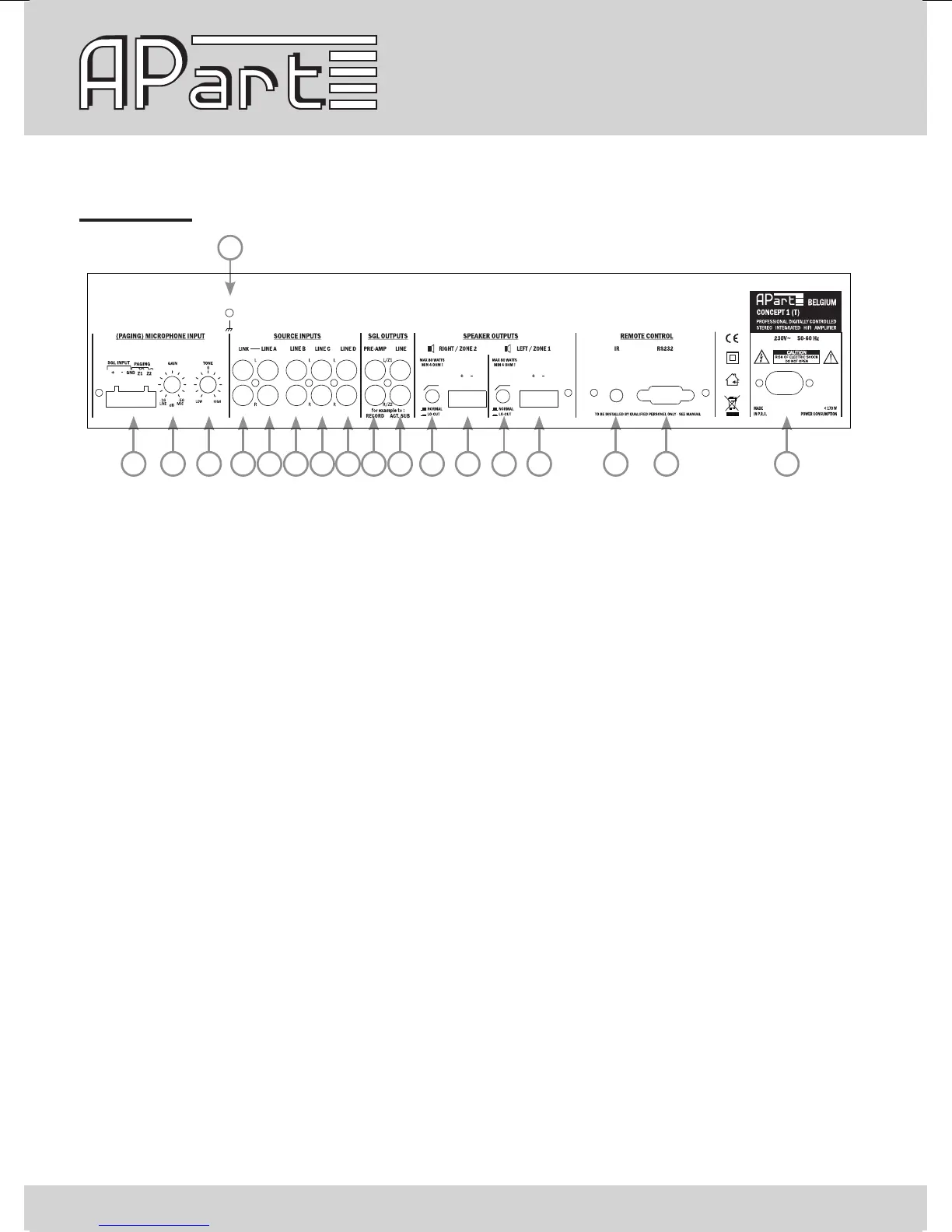
Rear panel
1 2 3 5 6 7 8 9 10 11 12 13 14 15 16 17 18
4
1) Microphone input: connect your (paging) microphone on this euroblock connector, connect the signal
on +, -, the screen on GND. Connect the eventual paging contacts between GND and Z1 (for zone 1) and
between GND and/or Z2 (for zone 2). The input gain can be adjusted with knob 2 between line and mic
level to avoid distortion.
2) Mic input gain control: mic input gain adjust
3) Mic input tone control: adjust the tone of the mic input between dark and bright
4) Ground connection: connect your safety ground lead or screens of your shielded input cables on this
screw if necessary.
5) Link output: the signal here is a copy of the line A input signal
6) Line A: stereo line RCA connector
7) Line B: stereo line RCA connector
8) Line C: stereo line RCA connector
9) Line D: stereo line RCA connector, a mini jack version of the line D input is available on the front panel.
Only use one of the two input’s at the same time.
10) Pre-amp out: these RCA connectors offer a level line out signal, before the master volume. It can be
used for recording or induction loop systems
11) Line out: these RCA connectors carry the line level signal after passing the volume control and limiter
circuit. This is an ideal way to connect to active subwoofers or extra power ampliers