CRS 40 V2
Installation, operation and service manual M2019/02a
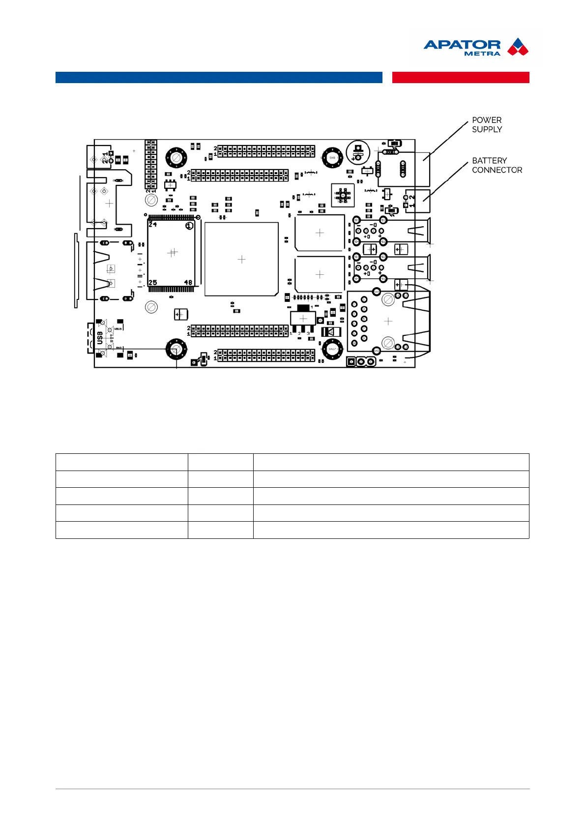
Table 1: LED signalization of operational states of control unit B
RED (OLIMEX A20) shines Unit B is connected to power supply
GREEN (OLIMEX A20) flashes Unit is working
YELLOW (OLIMEX A20) shines Charging of the backup battery
RED (radio module) shines Radio module RFCC1101 is on
GREEN (radio module) flashes Obtaining data from the units A
5.2. INSTALLATION OF COLLECTING UNITS A
It is recommended to place one collecting unit A to every entrance of residential building. Theoretically, the
building can be covered with smaller quantity of collecting units. There can be a problem to read the data
from some read devices (radio modules for water meters and heat cost allocators) in such case. As a result,
the read device can be interpreted as missing even when it is okay and functional.
For more information about recommended installation positions in the most common types of buildings, see
chapter 13. Installation methods.
Connection of collecting unit A to control unit B must be verified at the installation site (indicated by red LED
switching off on the radio module RFCC1101 after power supply connection). It is also recommended that
unit A receives the data from read devices (radio modules, heat cost allocator). Data receiving is indicated by
green LED blinking (approx. 1 min.).
If collecting unit A is not connected to control unit B after power supply connection, try to restart unit A using
RESET button on the radio module printed circuit board (see Illustration 4: Layout of the radio module
RFCC1101).
After the actual installation of units A, it is appropriate to connect to unit B and verify successful
communication. Click to <Units A> link on main page. Here you can find the list of connected collecting units
A ,including the time from last communication with control unit B, signal strength and number of connections.
For more information, see chapter 10.4 List of units A connected to reading network.
13 / 57
 Loading...