CRS 40 V2
Installation, operation and service manual M2019/02a
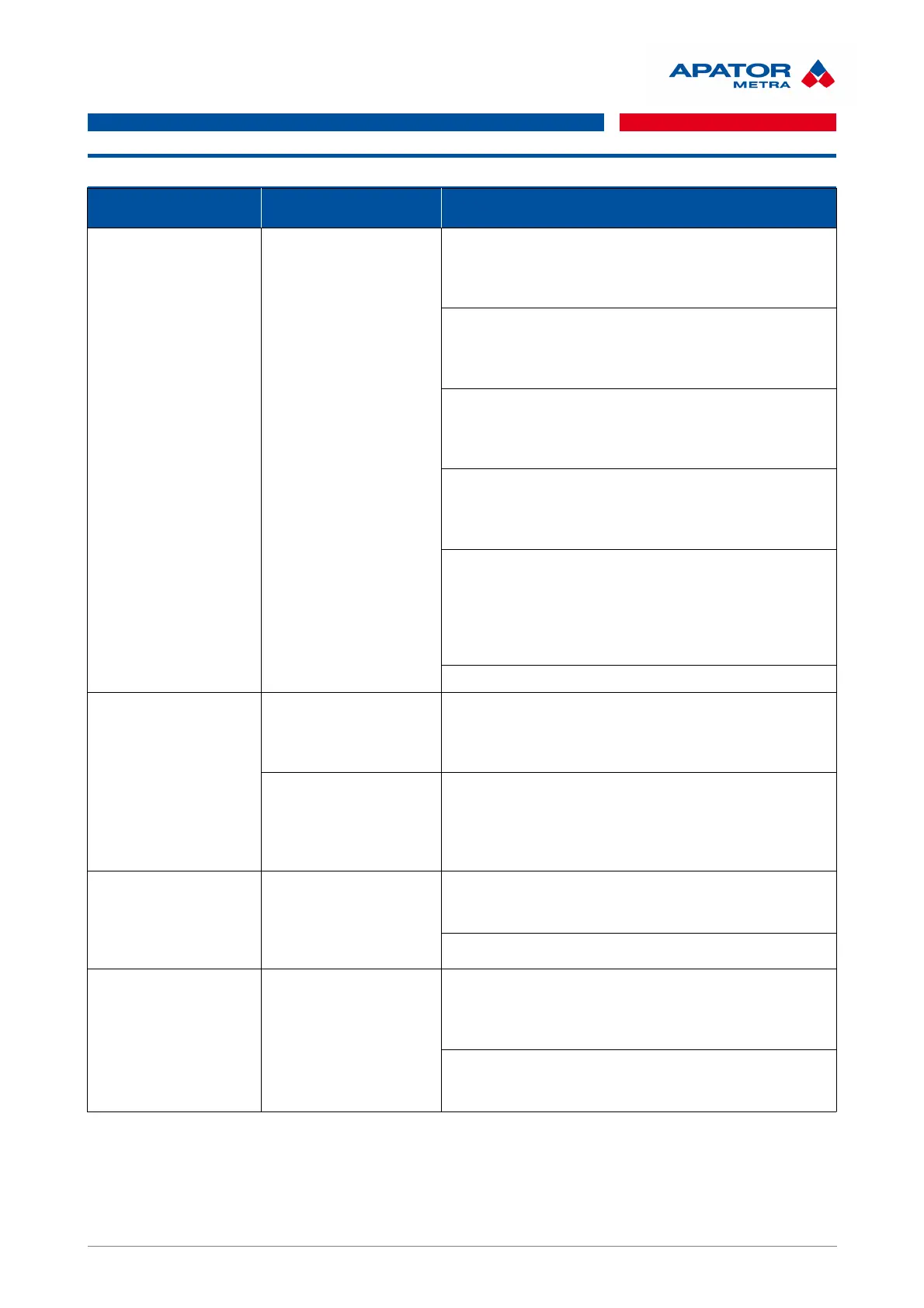
8. TROUBLESHOOTING
DESCRIPTION PROBLEM INDICATION RECOMMENDED SOLUTION
Collecting unit A can
not establish the radio
contact with control
unit B
Red LED on radio
module of unit A lights
even after restart
The system is designed for remote communication. If
units A and B equipped with antenna are located in
close proximity, receiver is “overload”. Place the
collecting unit A further from control unit B.
Collecting unit A is too far from control unit B or barrier
impermeable for 868 MHz radio waves is located
between them. Place collecting unit A closer to the
control unit B.
Check that DIP switch configuration is the same at both
unit A and B. If not, change DIP switch to the same
configuration. For more information, see chapter 6.2.
Configuration of multiple overlapping network.
Check that DIP switch configuration is the same at both
unit A and B. If not, change DIP switch to the same
configuration. For more information, see chapter 6.2.
Configuration of multiple overlapping network.
Check that DIP switch is not in ON-ON-ON-ON
configuration neither at unit A not unit B. This layout is
reserved for test mode and must not be used. If
configuration ON-ON-ON-ON is used, change it. For
more information, see chapter 6.2. Configuration of
multiple overlapping network.
Check that the B unit works correctly.
Connection of
collecting unit A and
control unit B is
unstable
Red LED blinks
irregularly at unit A
Connection is unstable if units are close to their limits
(too far or too close). Solve it as described above.
Place collecting unit A closer (or further) to control
unit B.
Red LED blinks
regularly at unit A
Power supply is not sufficient. It can be caused by weak
batteries or by power supply failure (unit is switched on
but restarted when tried to transmit). Change the
batteries or check the connection to electrical
network.
Collecting unit A or
control unit B does not
work
Both LED on radio
module are switched off
even after disconnecting
and connecting of power
supply
Power supply malfunction. Battery voltage must be at
least 2,2 V. Change the batteries or check the
connection to electrical network.
Unit malfunction. Send it to manufacturer to repair.
Control unit does not
contain any data from
read devices
There are no data on
the main page
Verify that red LED is off in units A (units are connected)
and green LED blinks in irregular interval of minutes
(data receiving indication). If the unit A does not receive
any data, there are displayed no data at unit B.
Check that unit A is not connected to another reading
network (see chapter 6.2. Configuration of multiple
overlapping network).
19 / 57
 Loading...