27
Part II: Trouble-Shoot Guide
For Newly Installed RO System
After installation, if you encounter any of the problems described below, please follow this guide to trouble-
shoot. In most cases, the problem is quickly solved by following this guide.
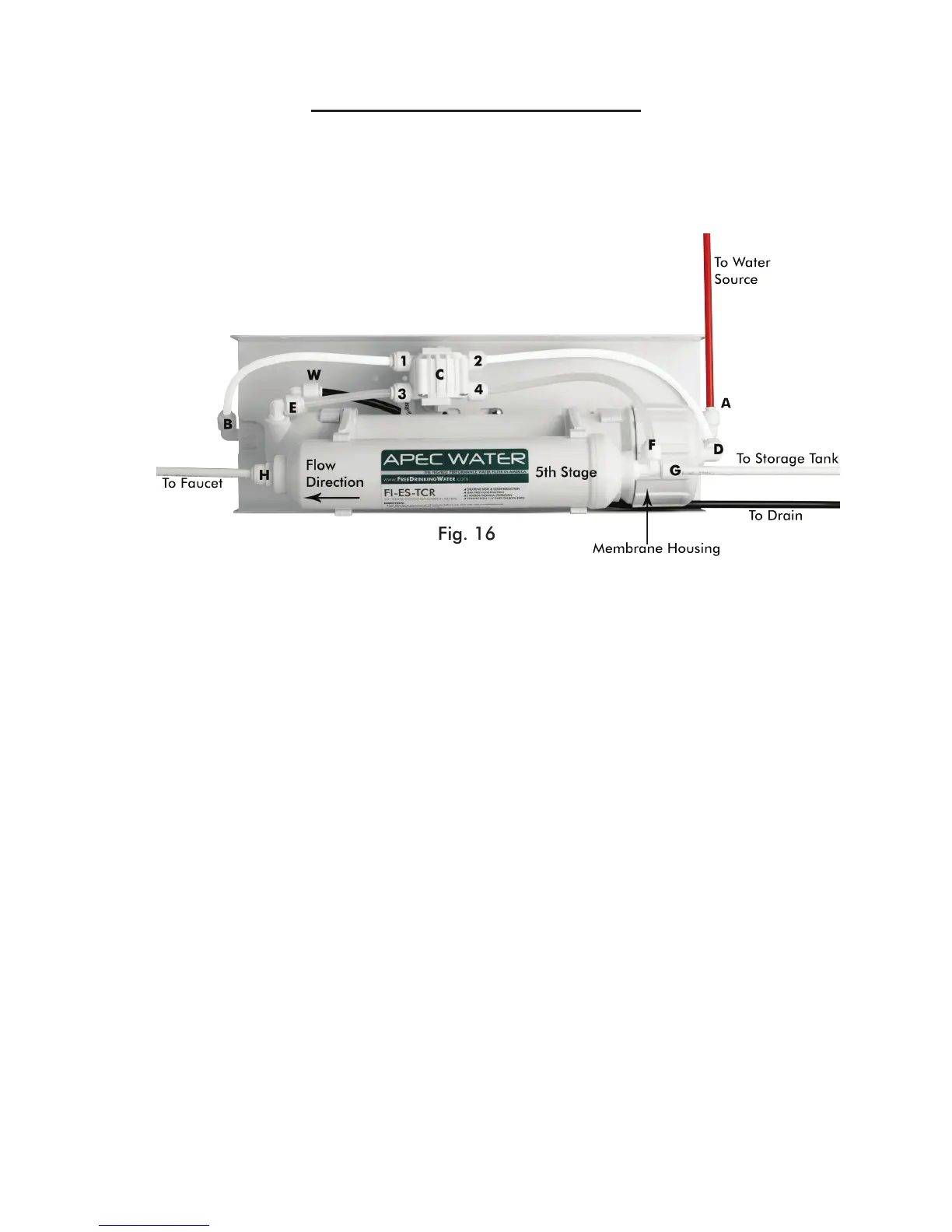
ROES System’s Head Diagram (w/o Pump)
ROES System’s Head Points Identication:
Point A: Feed water inlet into Stage-1 filter
Point B: Stage-3 filter’s output port
Point C
: Automatic-Shut-Off (ASO) valve.
Point D: Stage-4 Membrane housing inlet port. Feed water from stage-3 filter enters the Membrane at
this port.
Point E: Check Valve. The filtered water from the Membrane passes through this Check Valve
before entering the storage tank. The Check Valve blocks the tank water from back-flowing into
the membrane.
Point F:
T-fitting on Stage-5 filter. This end of the T-fitting connects to the CLEAR pure water line.
Point G: T-fitting on the Stage-5 filter. This other end of the T-fitting connects to the YELLOW pure water
line which goes to the tank’s valve.
Point H
: The output end of Stage-5 filter. Pure water leaves Stage-5 filter via this port, and flows onto the
dispensing faucet.
Fig. 16