Apeks ATX Second Stage Service Manual
9
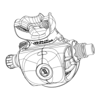
14. Fit a new, lubricated o-ring (26) onto the adjustable crown
(27). Press the adjustable crown, threaded end rst, into the
valve body. Using blunt end of the seat extractor tool, push
the adjustable crown into the valve body as far as it will go.
15. While holding the rim of the box bottom at eye level, turn
the adjustable crown orice in (clockwise) until the lever
drops about 4mm below the case rim. Then, turn the crown
counterclockwise until the lever is even with the case rim.
16. Add a new o-ring to the male end of the medium pressure
hose. Install a new, lubricated o-ring into the swivel end of
the hose
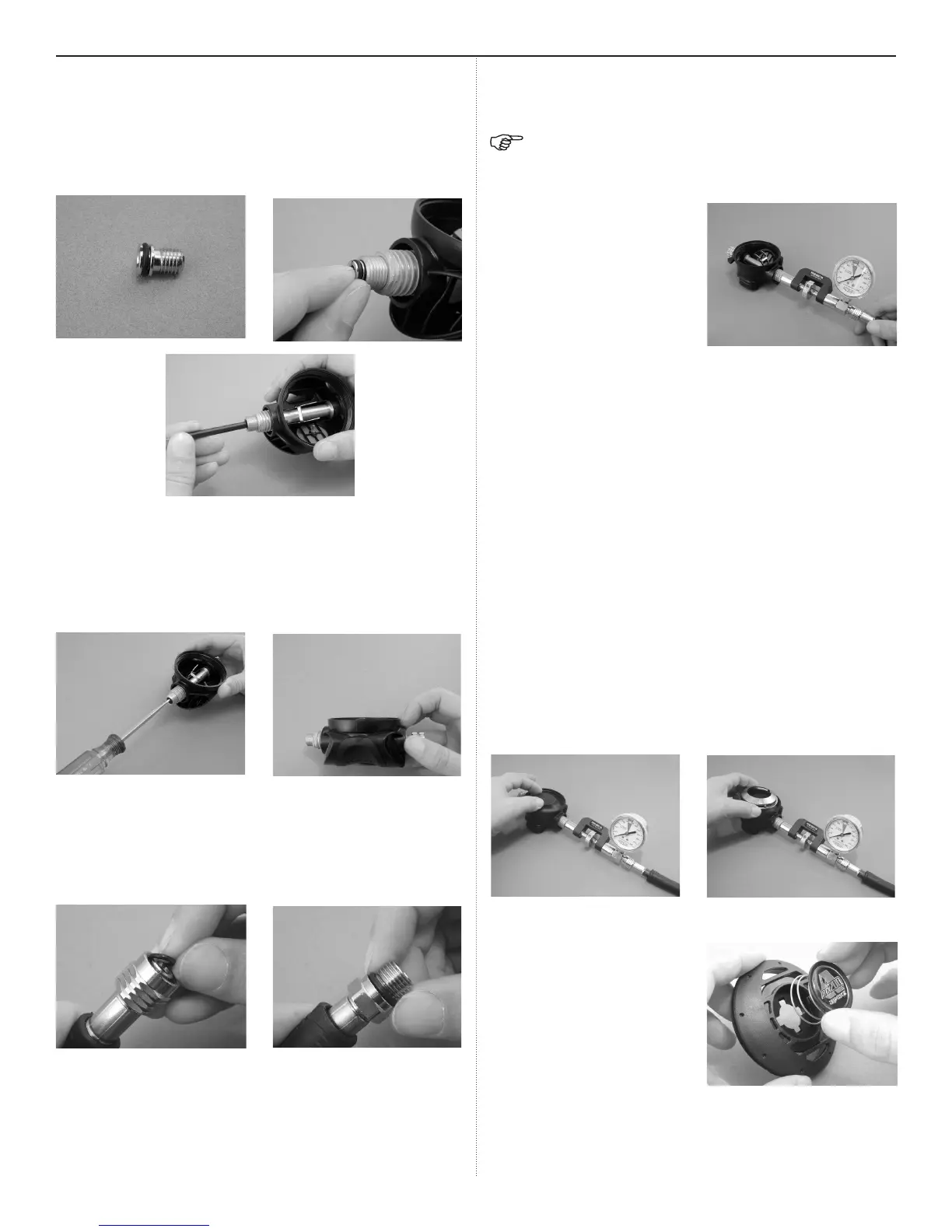
17. Adjust the lever height
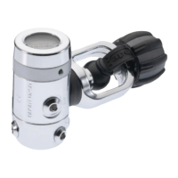
NOTE: The inline adjustment tool can be use with crowns
with a screwdriver slot or a hex hole. Make sure the inline
tool is set to use the appropriate tting.
a. Attach the Aqua
Lung in-line tool
(p/n 100190) to the
second stage. It can
accommodate both
the crown orice with
the 5mm hex and the
crown orice with the
slot. The tool is shown
with the optional in-line medium pressure gauge (p/n
111605).
b. Attach the swivel end of the medium pressure hose
to the other end of the inline tool. Attach the male end
of the hose to a properly adjusted rst-stage regula-
tor (135±5). Attach the rst-stage to a fully charged
cylinder. Slowly open the cylinder valve to pressurize
the regulator.
c. Press inward on the adjustment wheel of the inline
tool. Slowly rotate the adjustment wheel until the inline
tool engages the crown orice. Turn the crown in until
the lever drops approximately ¹₄”. This will “coin” the
rubber seat to help achieve a better seal. Now back
the crown orice out (counterclockwise). The lever will
raise. Continue until the lever is even with the rim of
the box bottom.
18. Position the diaphragm (6) into the box bottom (7). Using
your nger, work the edges of the diaphragm into place so it
sits evenly in the box bottom. Install the diaphragm cover (5)
into the case, over the diaphragm.
19. Place the small diameter
end of the purge spring
(3) onto the purge but-
ton (2). Orient the case
cover with the slotted
openings pointing to the
right. Properly align the
purge button and press
it into the case cover
until it snaps into place.
 Loading...