Apeks Supercritical: The Duplex™ Installation Manual
15
Revision Date 04/11/2019
3.3. Set Up and Assembly
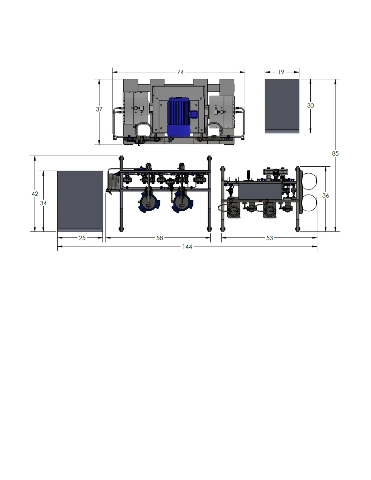
3.3.1. Standard Layout/Footprint with Indoor Chiller
3.3.2. Coolant Line and Chiller Set Up
3.3.2.1. Separator Coolant Loop – The separator coolant loop will incorporate the Separator
Chiller, the diaphragm compressor and the Separator Vessel/Control Stand.
3.3.2.1.1. Chiller Outlet to Diaphragm Compressor – The hose on the chiller outlet will
connect to the oil heat exchanger on the diaphragm pump.
3.3.2.1.2. Diaphragm Compressor to Separator Stand – The hose coming from the brass
tee on the diaphragm compressor will connect to the water valve with the flow switch
on the separator stand.
3.3.2.1.3. Separator Stand to Chiller Inlet – The hose on the chiller outlet will connect to the
water valve without the flow switch on the separator stand.
3.3.2.2. Extractor Coolant Loop – The extractor coolant loop will incorporate the Extractor Chiller
and the Extractor Vessel Stand.
3.3.2.2.1. Chiller Outlet to Extractor Stand – The hose on the chiller outlet will connect to the
temperature control heat exchanger on the extractor stand.
3.3.2.2.2. Extractor Stand to Chiller Inlet – The hose on the chiller inlet will connect to the
flow switch on the extractor stand.
3.3.2.3. Initial Fill – This step will need to be performed after the chillers electrical connection has
been made and the chiller is connected to the main control enclosure. (See Electrical
Requirements section, page 21.)
Figure 7: Standard Layout/Footprint with Indoor Chiller