4
5
FLIGHT First Stage Regulator Maintenance Manual
FLIGHT First Stage Regulator Maintenance Manual
COPYRIGHT NOTICE
This manual is copyrighted, all rights reserved. It may not, in
whole or in part, be copied, photocopied, reproduced, translated,
or reduced to any electronic medium or machine readable form
without prior consent in writing from Apeks Marine Equipment Ltd.
It may not be distributed through the internet or computer bulletin
board systems without prior consent in writing from Apeks Marine
Equipment Ltd.
©2011 Apeks Marine Equipment Ltd.
Flight First Stage Maintenance Manual
(AP4497 Issue 6)
INTRODUCTION
This manual provides factory prescribed procedures for the correct
maintenance and repair of the Apeks Flight rst stage regulators. It
is not intended to be used as an instructional manual for untrained
personnel. The procedures outlined within this manual are to be
performed only by personnel who have received factory authorised
training through an Apeks Service & Repair Seminar. If you do not
completely understand all of the procedures outlined in this manual,
contact Apeks to speak directly with a Technical Advisor before
proceeding any further.
WARNINGS, CAUTIONS & NOTES
Pay special attention to information provided in warnings,
cautions, and notes that are accompanied by one of these
symbols:
WARNINGS indicate a procedure or situation
that may result in serious injury or death if
instructions are not followed correctly.
CAUTIONS indicate any situation or technique
that will result in potential damage to the
product, or render the product unsafe if
instructions are not followed correctly.
NOTES are used to emphasise important points, tips,
and reminders.
SCHEDULED SERVICE
It is recommended that the Apeks Flight rst stage regulators should
be examined annually regardless of usage. A full service should be
performed every two years.
However, If at all unsure about the correct functioning of
the Apeks rst stage, then it must be ocially inspected
immediately.
All service and inspection details need to be documented in the
Regulator Service Record in the back of the Owner’s Manual to
keep the Limited Lifetime Warranty in eect.
An Ocial Inspection consists of:
1. A pressurised immersion test of the entire unit to
check for air leakage.
2. Checking for stable medium pressure that is within
the acceptable range.
3. Checking that all parts are tightly fastened together
and that no parts are loose.
4. A visual inspection of the composite Large Spring Adjuster
(1) and Composite Diaphragm Clamp (4), checking for any
visual cracking, marks or signs of damage or wear. (See
page 7. This can be done by peeling o the protector cap
(15) and inspecting all external faces where possible ithout
removal or adjustment.
5. A visual inspection of any lters for debris or dis-
colouration.
6. Pulling back hose protectors and checking that the
hoses are secure in the hose crimps.
If a regulator fails steps 1,2,3 or 4 the entire regulator should be
serviced. If a regulator fails 5 it will be up to the technician’s
discretion whether or not a full service is required. Failure of step
6 requires replacement of the Hose.
GENERAL GUIDELINES
1. In order to correctly perform the procedures outlined
in this manual, it is important to follow each step
exactly in the order given. Read over the entire
manual to become familiar with all procedures and
to learn which specialty tools and replacement parts
will be required before commencing disassembly.
Keep the manual open beside you for reference while
performing each procedure. Do not rely on memory.
2. All service and repair should be carried out in a work
area specically set up and equipped for the task.
Adequate lighting, cleanliness, and easy access to
all required tools are essential for an ecient repair
facility.
3. During disassembly, reusable components should be
segregated and not allowed to intermix with non-
reusable parts or parts from other units. Delicate
parts, including inlet ttings and valve seats which
contain critical sealing surfaces, must be protected
and isolated from other parts to prevent damage
during the cleaning procedure.
4. Use only genuine Apeks parts provided in the 1st stage
service kit (AP0250). DO NOT attempt to substitute an
Apeks part with another manufacturer’s, regardless of any
similarity in shape or size.
5. Do not attempt to reuse mandatory replacement
parts under any circumstances, regardless of the
amount of use the product has received since it was
manufactured or last serviced.
6. When reassembling, it is important to follow every
torque specication prescribed in this manual,
using a calibrated torque wrench. Most parts are
made of either marine brass or plastic, and can be
permanently damaged by undue stress.
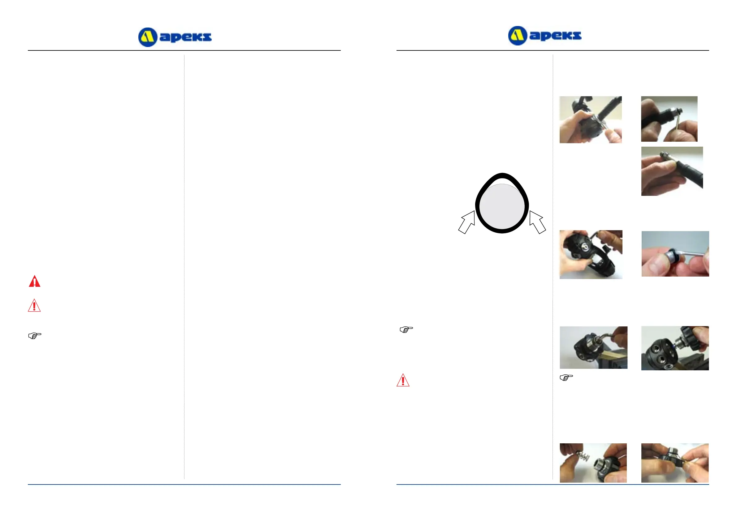
Pinch Method
Press upwards on
sides of ‘O’ Ring to
create a protrusion.
Grab ‘O’ Ring or
insert ‘O’ Ring tool
at protrusion.
Removal of hose
Removal of Blanking Plugs
GENERAL CONVENTIONS
Unless otherwise instructed, the following terminology and
techniques are assumed:
1. When instructed to remove, unscrew, or loosen a
threaded part, turn the part anti-clockwise.
2. When instructed to install, screw in, or tighten a
threaded part, turn the part clockwise.
3. When instructed to remove an ‘O’ Ring, use the pinch
method (see gure below) if possible, or use a brass,
aluminium or plastic ‘O’ Ring removal tool. Avoid using
hardened steel picks, as they may damage ‘O’ Ring
sealing surfaces. All ‘O’ Rings that are removed are
discarded and replaced with brand new ‘O’ Rings.
4. The following acronyms are used throughout the
manual: MP is Medium Pressure; HP is High Pressure;
PN is Part Number.
5. Numbers in parentheses reference the key numbers
on the exploded parts schematics. For example, in the
statement, “...remove ‘O’ ring (4) from...”, the number 4
is the key number to the Spring Carrier ‘O’ Ring.
DISASSEMBLY PROCEDURES
NOTE: Before performing any disassembly, refer
to the exploded parts drawing, which references all
mandatory replacement parts. These parts should be
replaced with new, and must not be reused under any
circumstances - regardless of the age of the regula-
tor or how much use it has received since it was last
serviced.
CAUTION: Use only a plastic, brass or aluminium
‘O’ Ring removal tool (PN AT79) when removing
‘O’ Rings to prevent damage to the sealing surface.
Even a small scratch across an ‘O’ Ring sealing
surface could result in leakage. Once an ‘O’ Ring
sealing surface has been damaged, the part must be
replaced with new. DO NOT use a dental pick, or
any other steel instrument.
2. Pull back the two Hose
Protectors and inspect
the Hose Crimps.
If either Crimp is
damaged or the Hose is
pulling out of the crimp
then the Hose must be
replaced.
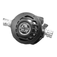
1. Using the appropriate spanners, remove all of the hoses
from the rst stage. Refer to 2nd stage manual for removal
of the 2nd stage and ‘O’ ring removal. Exercise caution not
to scratch the ‘O’ ring groove. Remove the ‘O’ ring from the
Hose Nut end of the Hose.
3. Using a 5mm Allen key remove all of the MP and HP
Blanking Plugs and remove all of the ‘O’Rings.
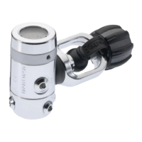
Removal of DIN Connection.
4. Using the First Stage Work Handle Tool (PN AT 48), secure
the Regulator in a bench xed vice. Using a 6mm Allen Key
Unscrew the Din Handwheel / Balance Chamber Assembly
from the 1st Stage Body.
5. Separate the HP Valve (16) and Spring (17) from the end of
the Balance Chamber (19) and remove the ‘O’Ring, taking
care not to scratch the O-Ring Groove.
NOTE: The Din Handwheel / Balance Chamber Assembly
may not unscrew as one component. In some cases the DIN
Bolt (24) may unscrew from the Din Connector (21). If this
happens remove the DIN Moulded Handwheel (22) and
use a 22mm spanner or deep socket to unscrew the DIN
Connector.

 Loading...