10
11
FLIGHT First Stage Regulator Maintenance Manual
FLIGHT First Stage Regulator Maintenance Manual
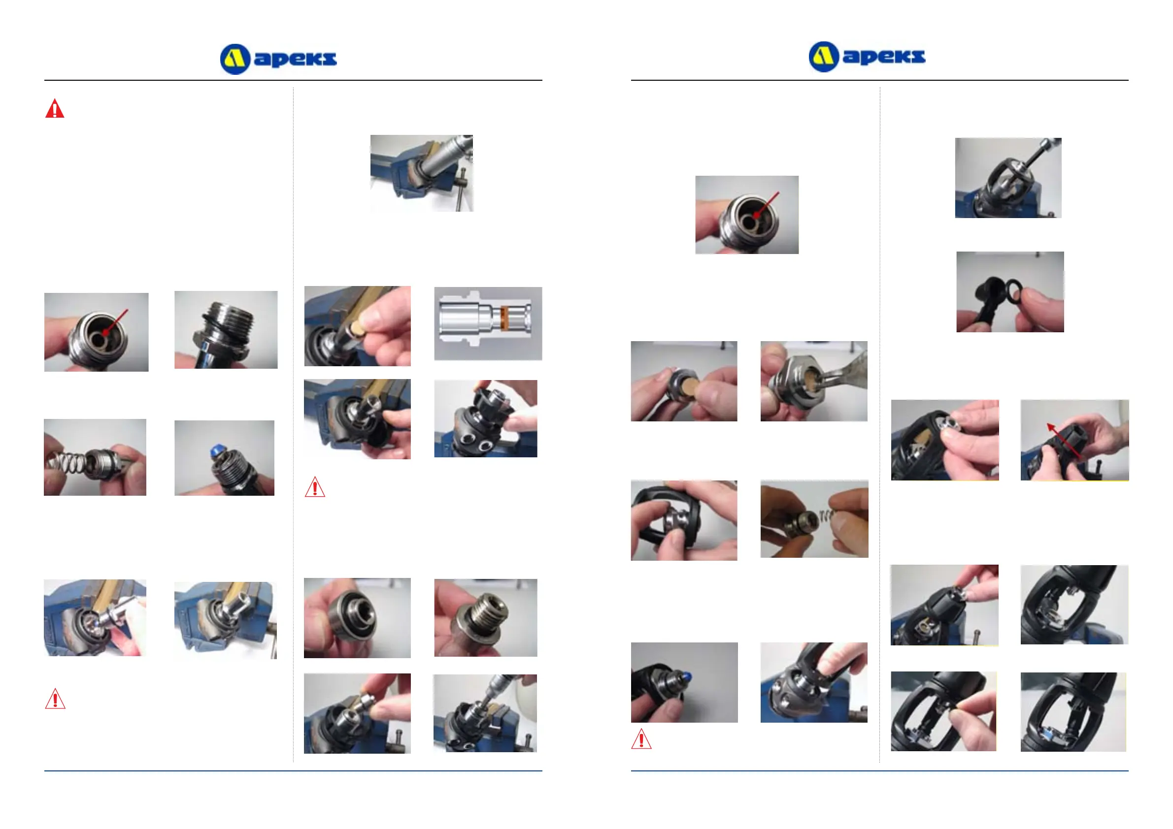
9. Install a new ‘O’ ring (18) into the Balance Chamber (19)
and a new ‘O’ ring (20) onto the DIN Connector (21).
10. Insert the Spring (17) onto the end of the Balance Chamber
(19) . Insert a new HP Valve (16) into the Spring (17).
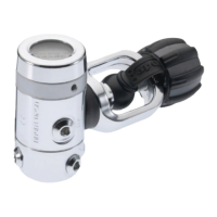
13. Insert a new DIN Filter (23) into the DIN Connector (21),
ensuring that the recessed side is facing down. Fit the
bottom of the Hood (15) onto the Jacket ensuring correct
alignment. (10). Slide the DIN Moulded Handwheel (22)
onto the DIN Connector (21).
Fitting of DIN Connection
WARNING: The Diaphragm Clamp Tool (AT71) has
three node points that engage on the Composite
Diaphragm Clamp (4). Ensure that these nodes are
correctly aligned into the Composite Diaphragm
Clamp (4) and that steady pressure is aplied to the
top of the tool whilst slowly torquing to 20 N/m (or
15 ft/lbs) to prevent the Tool from Slipping.
Excessive torque on this component will result in
damage and failure. Do not overtighten past 20 N/m
(or 15 ft/lbs). A calibrated torque wrench must be
used. Ensure that the torque wrench is the correct
scale, size and load
11. Carefully insert the HP Valve (16) into the Flight Body (9)
making sure that it slides onto the shaft of the Valve Lifter
(8). Hand tighten the DIN Connector (21).
12. Using a 22mm Deep Socket and a torque wrench, torque the
DIN Connector (21) to 25 N/m (or 18 ft/lbs).
CAUTION: Ensure that the DIN Filter (23) sits at
and is fully pressed down in the DIN Connector (21)
,
otherwise damage may be caused when tting the DIN
Bolt (24)
.
14. Install two new ‘O’ Rings (14 & 25) onto the DIN Bolt (24).
Using a torque wrench and a 6mm Allen key bit, carefully
torque the DIN Bolt to 25 N/m (0r 18 ft/lbs).
CAUTION: Care must be taken not to touch the face of
the H.P valve with mating part or nger nails, as this will
cause damage to the part.
16. Drop a new Disc Filter (28) into the Yoke Connector (27).
Using a pair of Circlip pliers insert the Circlip (29) into
the Yoke Connector (27) ensuring that it ts securely into
15. Install a new ‘O’ ring (18) into the Balance Chamber (19)
and a new ‘O’ ring (20) onto the Yoke Connector (27).
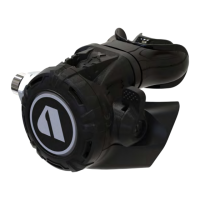
Fitting of Yoke Connection
17. Insert the Yoke Connector through the Yoke Clamp (31) and
t the spring (17) onto the end of the Balance Chamber (19).
18. Fit the bottom of the Hood (15) onto the Jacket ensuring
correct alignment. (10). Insert a new HP Valve (16) into
the Spring (17). Carefully insert the HP Valve (16) into the
Flight Body (9) making sure that it slides onto the shaft
of the Valve Lifter (8). Hand tighten the Yoke Connector
ensuring that it is square. (27).
19. Using AT74 Yoke Connector Socket and a long 6mm Allen
key bit, carefully torque the Yoke Connector to 25N/m.
20. Fit a new ‘O’ Ring (34) into the end of the Dust Cap (33).
21. Fit the loop end of the Dust Cap (33) onto the top of the
Yoke Covers (32). Ensure that the two lugs on the Dust Cap
t into the two recesses in the Yoke Covers. Slide and push
the Yoke Knob (35) onto the top of the Yoke Clamp (31).
22. Screw the Handwheel Hex Axle (36) through the Yoke
Knob (35) into the Yoke (31) until the end of the Axle is
engaged in the Knob. Turn the Yoke Knob (35) until the
Hex Axle (36) protrudes through the Yoke Clamp (31) so
that the Plastic Clip (30) can be t into the groove on the
Axle.
CAUTION: Care must be taken not to touch the face of
the H.P valve with mating part or nger nails, as this will
cause damage to the part.