8
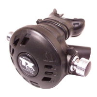
TX Second Stage Regulator Maintenance Manual
9
TX Second Stage Regulator Maintenance Manual
REASSEMBLY PROCEDURES
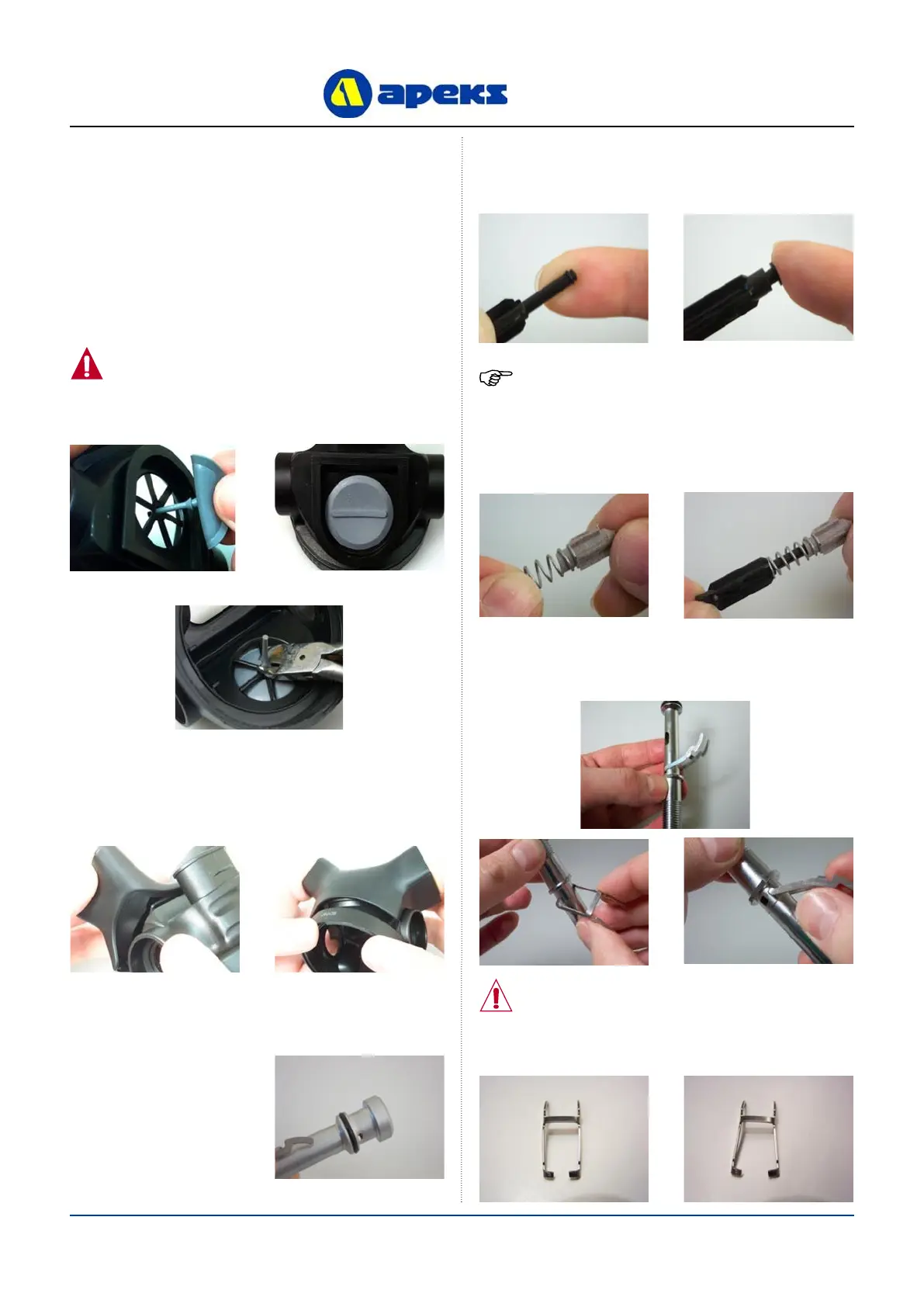
1. If the Exhaust Valve (15) was removed, replace by threading
the tail through the retaining hole on the outside of the Case
(9) until the barb engages on the inside. Align the rib so it is
horizontal. If the Valve is new, cut off the excess stem with
side cutters leaving approximately 5mm (0.196”) of the tail
behind.
2. Orientate the Exhaust Tee (16) with the Case (9). Clip one
corner of the Tee onto the Case. Stretch the other corner
over the Case and then stretch the bottom of the Tee onto
the Case.
3. Install a new, lubricated
‘O’ Ring (8) onto the
Valve Spindle. (20).
4. Press a new, lubricated ‘O’ ring (24) onto the stem of the
Shuttle Valve (23). Press a new Rubber Seating (22) into
the front of the Shuttle Valve.
5. Fit the Valve Spring (25) onto the leading edge of the
Counterbalance Cylinder (26). Carefully guide the stem
of the Shuttle Valve through the Spring and into the
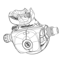
Fitting Exhaust Valve and Exhaust Valve Cover
Assembling and tting valve assembly
WARNING: Flooding may occur if the tail of
the valve is not fully pulled through. Check
that barb has engaged on inside of Case.
NOTE: Ensure Rubber Seating has been tted ush
with Shuttle Valve.
CAUTION: Ensure that Lever is not twisted
and that legs are parallel. Lever should
appear as that shown on the left, not as
shown on the right. If necessary, gently
squeeze legs together to straighten.
Counterbalance Cylinder.
6. If you removed the Lever, replace it so that it points
upwards when the air outlet hole points to the left with the
threaded end facing you.
 Loading...