5
XTX FSR & FST First Stage Regulator Maintenance Manual
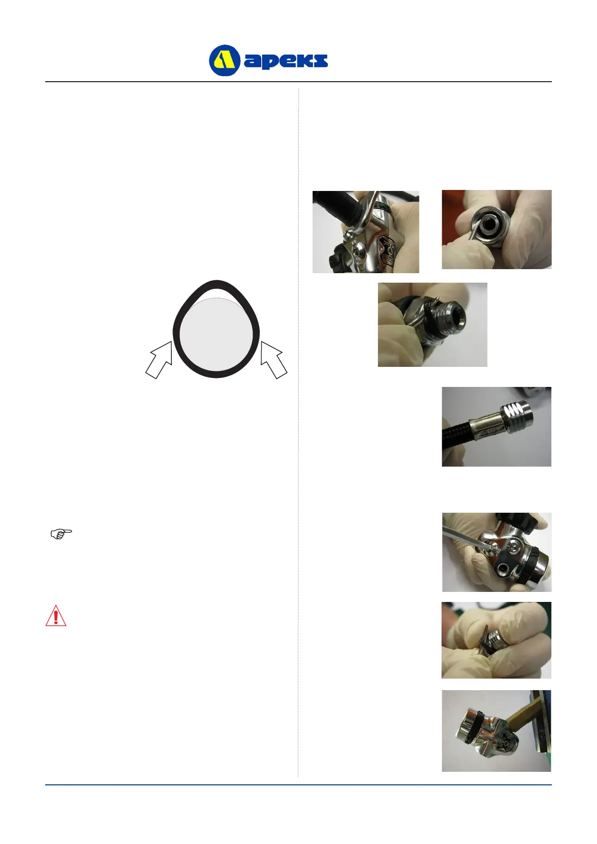
Pinch Method
Press upwards on
sides of ‘O’ Ring
to create a protru-
sion. Grab ‘O’ Ring
or insert ‘O’ Ring
tool at protrusion.
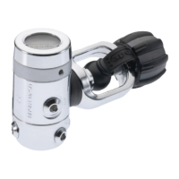
Removal of hose
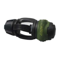
Removal of Blanking Plugs
GENERAL CONVENTIONS
Unless otherwise instructed, the following terminology and
techniques are assumed:
1. When instructed to remove, unscrew, or loosen a
threaded part, turn the part anti-clockwise.
2. When instructed to install, screw in, or tighten a
threaded part, turn the part clockwise.
3. When instructed to remove an ‘O’ Ring, use the pinch
method (see gure below) if possible, or use a brass,
aluminium or plastic ‘O’ Ring removal tool. Avoid using
hardened steel picks, as they may damage ‘O’ Ring
sealing surfaces. All ‘O’ Rings that are removed are
discarded and replaced with brand new ‘O’ Rings.
4. The following acronyms are used throughout the
manual: MP is Medium Pressure; HP is High Pressure;
PN is Part Number.
5. Numbers in parentheses reference the key numbers
on the exploded parts schematics. For example, in the
statement, “...remove ‘O’ Ring (4) from...”, the number
4 is the key number to the Spring Carrier ‘O’ Ring.
DISASSEMBLY PROCEDURES
NOTE: Before performing any disassembly, refer
to the exploded parts drawing, which references all
mandatory replacement parts. These parts should be
replaced with new, and must not be reused under any
circumstances - regardless of the age of the regula-
tor or how much use it has received since it was last
serviced.
CAUTION: Use only a plastic, brass or aluminium
‘O’ Ring removal tool (PN AT79) when removing
‘O’ Rings to prevent damage to the sealing
surface. Even a small scratch across an ‘O’ Ring
sealing surface could result in leakage. Once an
‘O’ Ring sealing surface has been damaged, the
part must be replaced with new. DO NOT use a
dental pick, or any other steel instrument.
1. Using a 9/16 spanner, remove all of the hoses from the
rst stage. Remove the ‘O’ Ring from inside the Hose
Swivel. Exercise caution not to scratch the ‘O’ Ring
groove. Remove the ‘O’ Ring from the Hose Nut end of
the Hose.
2. Pull back the two
Hose Protectors and
inspect the Hose
Crimps. If either
Crimp is damaged or
the Hose is pulling
out of the crimp then
the Hose must be
replaced.
3. Using a 5mm Allen
key remove all of the
MP and HP blanking
plugs.
4. Remove all of the
‘O’ Rings from the
Blanking Plugs.
5. Using the First Stage
Work Handle (PN
AT48) clamp the
regulator in a vice.
 Loading...