8
XTX FSR & FST First Stage Regulator Maintenance Manual
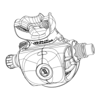
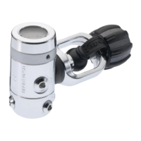
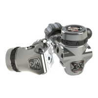
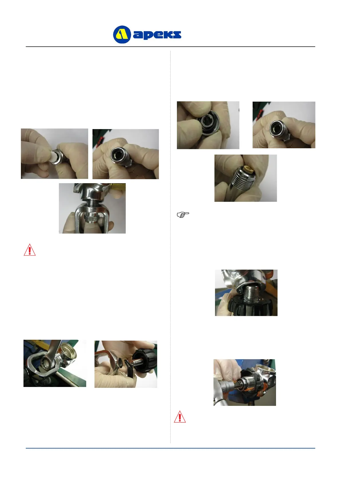
Assembling and tting of Yoke Connection
NOTE: Ensure that the ‘O’ Ring is retained in the
Connector after the Conical Filter has been tted.
CAUTION: If the Yoke Clamp Assembly is not
held vertically whilst it is screwed into the
Valve Body, the ‘O’ Ring in the end of the Yoke
Clamp Connector may not remain in the correct
position.
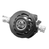
Assembling and tting of DIN Connection
CAUTION: If the Handwheel Connector
Assembly is not held vertically whilst it is
screwed into the Valve Body, the ‘O’ Ring in the
end of the Handwheel Connector may not remain
in the correct position.
1. Insert a new Disc Filter (21) with the smooth side out,
into the Yoke Clamp Connector (20). Install a new
lubricated ‘O’ Ring (12) into the end of the Connector.
2. Insert the Yoke Clamp Connector (20) through the
Yoke Clamp (19). With the Valve Body held so that
the inlet connection port points down, screw the Yoke
Clamp Connector into the Valve Body (11) until nger
tight.
3. Secure the Valve Body (11) back into the vice using the
First Stage Work Handle (PN AT48). Tighten the Yoke
Clamp Connector using a 3/4” A/F spanner. Install the
Protective Cap (22) with the logo facing outwards, onto
the Yoke Clamp (19). Screw the Yoke Clamp Screw
(24) back into the Yoke Clamp (19), until the Protective
Cap (22) is retained in place.
4. Install a new ‘O’ Ring (23) into the face of the
Handwheel Connector (30). Install a new lubricated
‘O’ Ring (12) into the opposite end of the Connector.
Install the Conical Filter (35) into the Connector,
through the ‘O’ Ring.
5. Insert the threaded end of the Handwheel Connector (30)
through the threaded end of the Handwheel (29). With
the Valve Body held so that the inlet connection port
points down, screw the Handwheel Connector into the
Valve Body (11) until nger tight.
6. Secure the Valve Body (11) back into the vice using
the First Stage Work Handle (PN AT48). Tighten the
Handwheel Connector (30) using a 6mm Allen key bit
in a torque wrench to 20 Nm.
 Loading...