Installation and Operation Manual
ECN: 003155
Date: 06/4/2013
42
AC-SmartStart-7608-Series_IOM Rev 04
LAN Module & Communications
The Unit Setup dialog contains the following items:
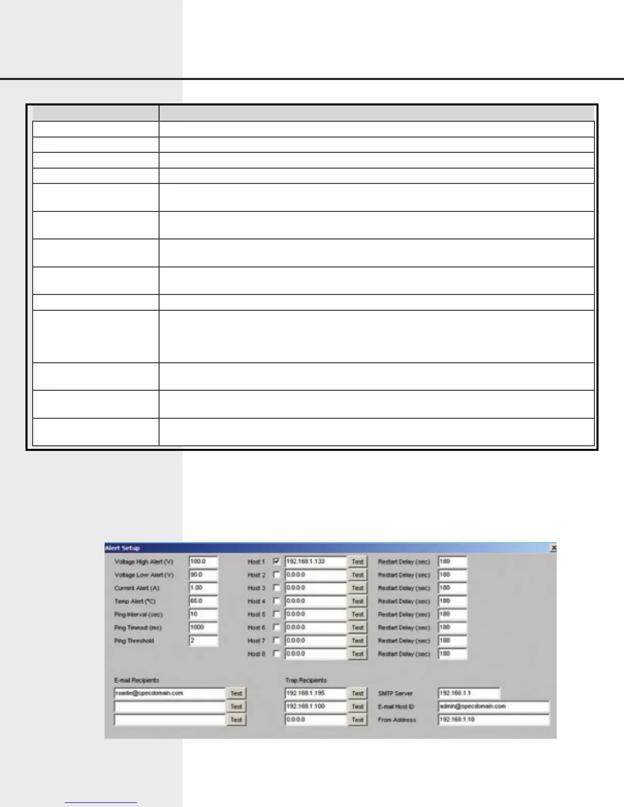
7.8.3 Alert Setup
The Alert Setup dialog lets the user set up and maintain conditions that cause alerts,
recipients who receive alerts, and other information related to alerts.
Figure 7.14 Web Interface Alert Setup
Item Function
Unit Name User-defined descriptive name of the unit.
PDU Address Number between 0-255, identifies the PDU.
Master/Slave Configures the unit for standalone, master, or slave operation.
Baud Rate Baud rate of the serial interface.
Current Limit A Shown as “Current Limit” on 1x8 units – indicates the maximum allowable current draw for
channel A, expressed in Amps.
Current Limit B Not shown on 1x8 units – indicates the maximum allowable current draw for channel B, ex-
pressed in Amps.
Under Voltage Setpoint A Shown as “Under Voltage Setpoint” on 1x8 units – indicates the minimum allowable input volt-
age for channel A, expressed in Volts.
Under Voltage Setpoint B Not shown on 1x8 units – indicates the minimum allowable input voltage for channel A, ex-
pressed in Volts.
Sequence Delay The delay between outlets when turning on or off sequentially, expressed in seconds.
Sequence The sequence in which outlets are turned on or off automatically. If an outlet number is not en-
tered in the sequence, the outlet will remain at its current state (on or off) until power is removed
from the unit, or circuit breaker is turned off. Each outlet not entered in the sequence is set to
operate in a manual operation mode.
Outlet Names Identifying names for each outlet. These names are displayed in the Outlet Control dialog win-
dow.
Group Names Identifying names for outlet groupings. These names are displayed in the Outlet Control dialog
window.
Group Outlets Specify the outlet number associated with the given outlet grouping. Up to four outlets can be
turned on or off simultaneously.