50
th
Anniversary 2500 Bus Compressor API
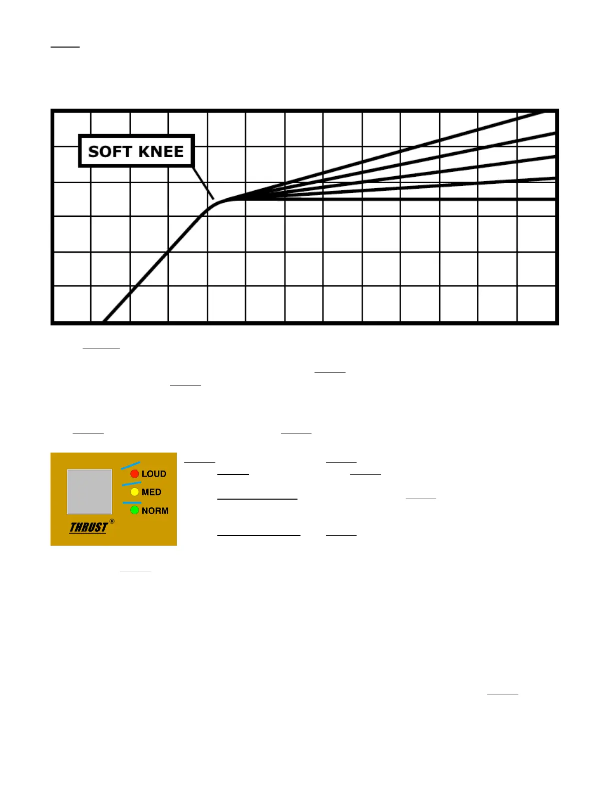
SOFT: Rounded response curve
• Gradual onset of compression (fade-in up to the set ratio)
• Similar to an “over-easy” type knee
• More transparent
• The green LED illuminates when engaged
5.1.2
THRUST
®
The 50
th
Anniversary 2500 includes API’s patented
THRUST
®
circuit that can be switched in or out as
needed. This places the
THRUST
®
filter before the RMS detector that decreases the compressor’s reaction
to low frequency content. The result is a noticeable increase of punch and low frequencies, but a
uniformly compressed signal. It’s the “little more punch” switch!
The
THRUST
®
circuit can be engaged using the
THRUST
®
switch.
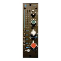
THRUST
®
: Cycle to select the
THRUST
®
function
• LOUD: Inserts the LOUD
THRUST
®
filter before the RMS detector
o Red LED
• MED (Medium): Inserts the MED
THRUST
®
filter before the RMS
detector
o Yellow LED
• NORM (Normal): No
THRUST
®
filter before the RMS detector (flat)
o Green LED
The patented
THRUST
®
circuit has been used for many years in the famed API 2500 Stereo Compressor,
ATI Paragon and Paragon II consoles, as well as the Pro6 Input Strip. This circuit places a filter in front
of the RMS detector with a slope of 10dB per decade (-3dB/8va), which is the inverse of the pink noise
energy curve. In acoustics, the pink noise curve is used to equalize energy vs. frequency over the
audio spectrum, as sound requires more low frequency energy than high frequency energy to sound
correct to your ear. In Hi-fi equipment, a “LOUDNESS” contour is used to equalize the music at lower
levels so it sounds correct. Even with this curve, there is still a substantial amount of low frequency
information compared to high frequency information in the audio signal path. When that signal is fed
into the RMS detector, the detector will process the signal into a DC control voltage based upon those
louder low frequencies, resulting in a control voltage that favors the low frequencies of the signal,
causing pumping and a loss of punch. Sometimes, this is not desirable. By engaging the
THRUST
®
switch,
this inverse filter is placed in front of the RMS detector, evening out the energy by lowering the energy
in the low frequencies and increasing the energy in the high frequencies, so each octave has the same
energy instead of each octave having half the energy as the one lower. This creates a unique