Specifications
36 Apollo GX50/60/65 Installation Manual
REAR CONNECTOR PINOUT
The GX60/65 includes two rear panel connectors, a 15 pin for the comm interface connections
and a 37 pin for the GPS navigation connections. The GX50 uses only the 37 pin connector.
The pinout for the connectors is listed in the following tables.
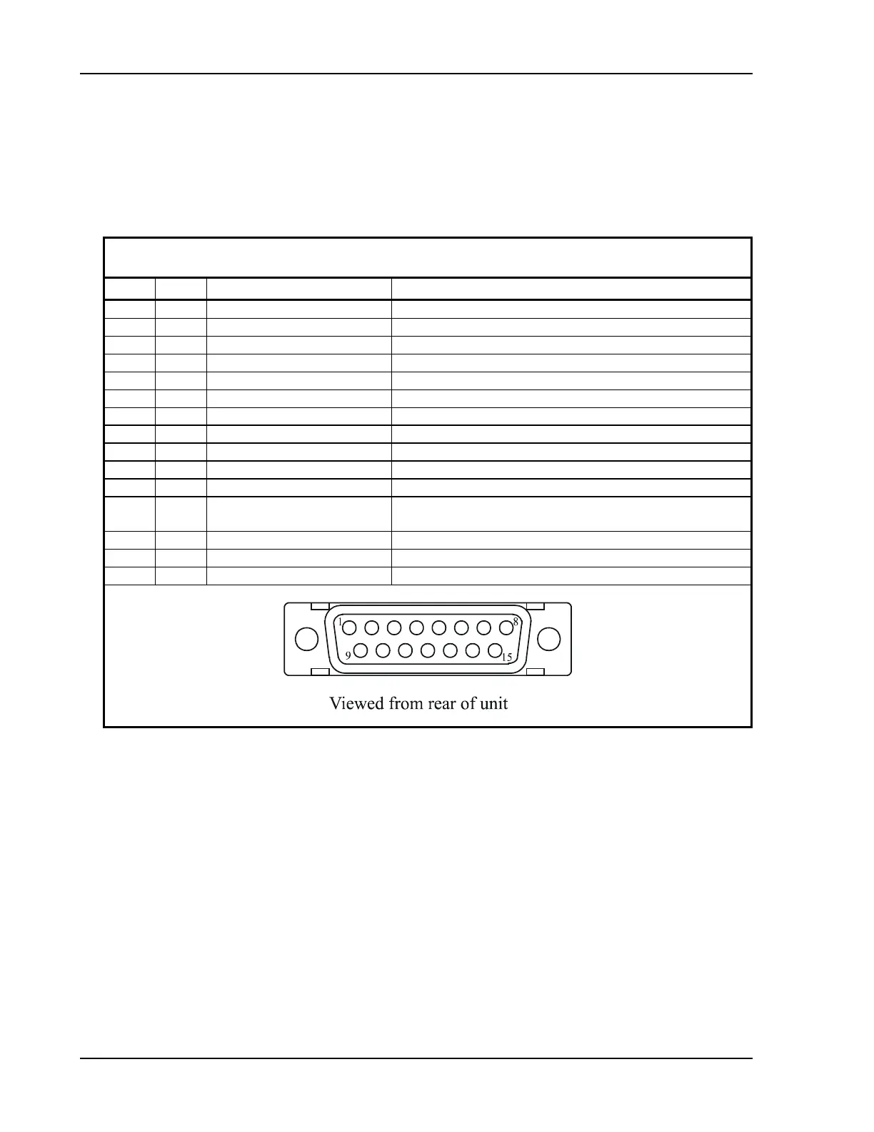
Table 2 Comm Interface Connector Pinout
Pin # I/O Connection Function
1 I Power + main DC power input
2 I Reserved do not connect
3 O Reserved do not connect
4 I TxKey transmit enable key, pulled low to transmit
5 -- NC do not connect
6 O Speaker speaker terminal output
7 I Mic ground microphone input ground connection
8 I Mic 1 microphone input #1
9 I Power ground main power ground input
10 I Reserved do not connect
11 O Reserved do not connect
12 I Intercom select intercom function select, pulled low to turn on the intercom
function
13 O Audio ground speaker and headphone ground connection
14 O Headphone headphone terminal output
15 I Mic 2 microphone input #2